6
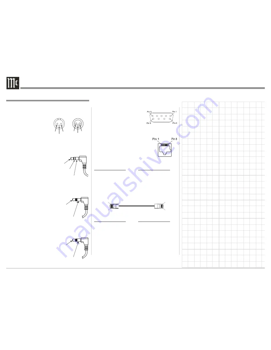
RS232 DB9 Connector Pin Layout
1. N/C
6. N/C
2. Data Out (TXD) 7. N/C
3. Data In (RXD)
8. N/C
4. N/C
9. N/C
5. Gnd.
Ethernet RJ45 Socket
1. Tranceive Data (+)
5. N/C
2. Tranceive Data (-)
6. Receive Data (-)
3. Receive Data (+)
7. N/C
4. N/C
8. N/C
Ethernet Cable - Straight Thru Connections
Pin Number - Wire Color
Pin Number - Wire Color
1. Orange/White
→
1. Orange/White
2. Orange
→
2. Orange
3. Green/White
→
3. Green/White
4. Blue
→
4. Blue
5. Blue/White
→
5. Blue/White
6. Green
→
6. Green
7. Brown/White
→
7. Brown/White
8. Brown
→
8. Brown
Ethernet Cable - Crossover Connections
Pin Number - Wire Color
Pin Number - Wire Color
1. Orange/White
→
1. Green/White
2. Orange
→
2. Green
3. Green/White
→
3. Orange/White
4. Blue
→
4. Blue
5. Blue/White
→
5. Blue/White
6. Green
→
6. Orange
7. Brown/White
→
7. Brown/White
8. Brown
→
8. Brown
XLR Connectors
Below is the Pin configuration for the XLR Balanced
Output Connectors on the MX121. Refer to the dia-
grams for connections:
PIN 1: Shield/Ground
PIN 2: + Signal
PIN 3: - Signal
PWR CTRL (Power Control)/Trigger Connectors
The MX121 Power Control Out/ Trigger Output Jacks
send an On/Off signal from 0 to +12 volts with a total
current up to 50mA when
connected to other Com-
ponents. A 1/8 inch stereo
mini phone plug is used for
connection to the Power
Control/ Trigger Outputs on
the MX121.
Data In and Output
The MX121 Data In receives
Remote Control Signals from
Source Components. The
MX121 Data Out sends Remote
Control Signals to McIntosh
Source Components. A 1/8 inch
mini phone plug is used for connection.
IR In Port Connector
The IR IN Port also uses a 1/8
inch mini phone plug and al-
lows the connection of external
IR Receivers to the MX121.
Connector and Cable Information
PIN 1
PIN 2
PIN 3
Connector and Cable Information
Pin 1
Pin 8
Pin 1
Pin 8
PIN 2
PIN 1
PIN 3
Input
Output
Data
Signal
Ground
IR Data
Control
Ground
+
12V DC
(Trigger
Control)
Ground
N/C
Содержание MX121
Страница 31: ...31 Setup Mode con t...
Страница 41: ...41 How to Operate the MX121 con t...


