background image

Adaptable – changing the view of 
the TRACE PRO AE Mixer 

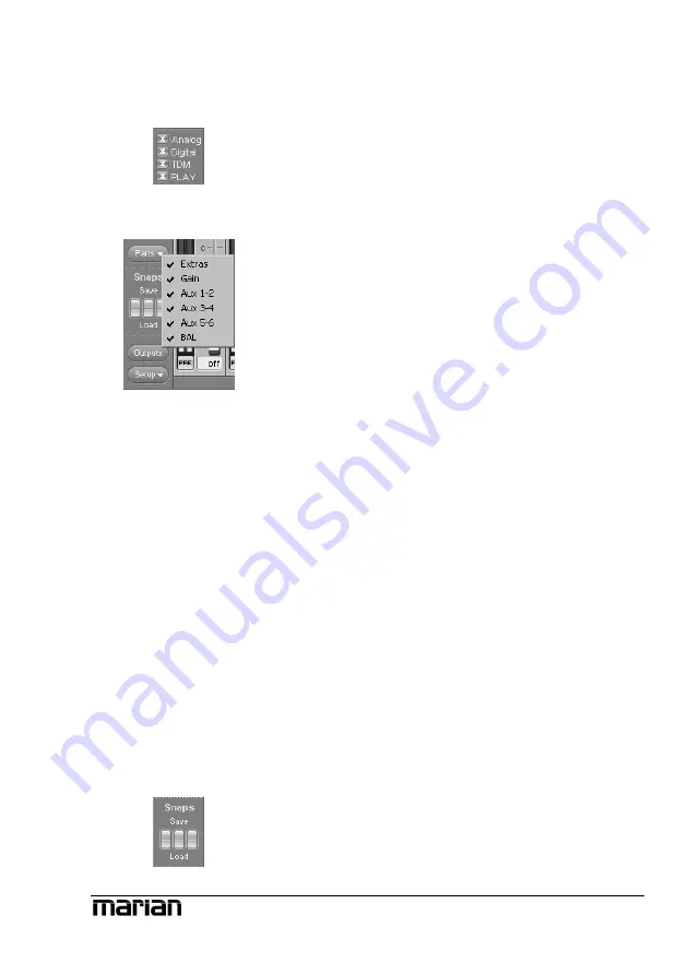
In the bottom left corner of the Mixer you can 
find four buttons for “Analog”, “Digital”, 
“TDM” and “PLAY”. These allow, with a click 
on the button, to hide or show the affected 
channels.  

In order to adjust the look of the Mixer 
according to your needs, single rows of control 
elements can be hid or shown with the help of 
“Parts”. This applies to all gain-, aux- or bal 
knobs and the “Extra” row.  

All these functions can be very handy for saving 
precious space on your computer screen. But 
they’re also useful if you wish to secure certain 
setups of faders or knobs from accidentally 
being changed.  

Of course, apart from all these functions, the 
window can be sized horizontally.  

If multiple TRACE PRO AE have been 
installed, you can bring up the Mixer of every 
sound system using the drop-down list in the top 
bar of the window. The lock-symbol in the upper 
right corner of the window prevents coverage by 
other windows. This way the Mixer is always on 
top and accessible. 

Y

y

ou may save certain visual configurations 

along with the current mixer settings in a 
“snapshot”. For this, click on one of the three 
buttons beneath “snaps” on the row “save”. If 

ou wish to recall a snapshot, click on the 

“load”-button situated beneath the previously 
saved snapshot. 


Z


Note: Hidden channels 

are still active, just like 
they were shown.


Z


Snapshots are 

independent of setups 
(see chapter “Saving and 
loading Setups”). Thus, 
they will not be 
overwritten by a setup.


15 

Содержание TRACE PRO AE

Страница 1: ...TRACE PRO AE User s Guide...

Страница 2: ...lly including photocopy translation recording or any information storage and retrieval system without permission in writing from MARIAN All trademarks are the property of the respective owners MARIAN...

Страница 3: ...puts 8 S PDIF Input 9 TDM SyncBus 9 The TRACE PRO AE in Detail 10 The first contact 10 The Mixer 11 What is it all about 11 The channels 12 Specialities of digital channel strips 14 The master channel...

Страница 4: ...4 ASIO Device Setup 36 The TRACE PRO AE in the connection with digital devices 38 Background 38 What is a clock 38 The rules in the digital audio world 39 Important notes on TRACE PRO AE and digital c...

Страница 5: ...zing 49 The TRACE PRO AE as hard disk recording system 50 Situation 50 What s there to care about 50 The TDM SyncBus Example 1 52 The situation 52 The solution 52 The TDM SyncBus Example 2 53 The situ...

Страница 6: ...udio data format unheard of so far Thanks to the unique Output Control extensive routings of all digital and analog single and mix signals are set up saved and recalled in a jiffy just like at a patch...

Страница 7: ...5...

Страница 8: ...2 kHz resolution 9 Complete balanced signal circuits for all connectors 9 20 channel DSP Mixer FPGA based 40 Bits Precision latency free 9 Flexible and extensive mix monitor and routing possibilities...

Страница 9: ...ng components are included and undamaged 9 1 x TRACE PRO AE PCI slot card 9 1 x XLR breakout cable for analog 9 1 x XLR breakout cable for digital 9 1 x connector cable for internal S PDIF input 9 1 x...

Страница 10: ...og in and output AES EBU Inputs and Outputs The stereo AES EBU in and output is connected to the TRACE PRO AE using a breakout cable Wordclock SuperClock Input Connect the Wordclock or SuperClock outp...

Страница 11: ...of the Mixer if CD is choosen in the drop down list TDM SyncBus If other MARIAN sound systems with TDM SyncBus option are installed they can be connected here using a TDM SyncBus cable Other MARIAN so...

Страница 12: ...tput Control of the TRACE PRO AE Furthermore you can save and load the setups for Mixer and Output Control Via Visualizations you may choose the different skins for Mixer and Output Control Info shows...

Страница 13: ...d digital the channels of the TDM SyncBus TDM In 1 to 4 and the playback channels of an audio application Play 1 2 to 7 8 The TRACE PRO AE offers an application with 16 playback channels as Play 1 2 t...

Страница 14: ...fects the range of the GAIN knob Beneath GAIN AUX 1 AUX 2 and so on are placed Pulling up knob AUX 1 will result in a volume increase of the signal in the signal sum aux 1 pulling up knob AUX 2 increa...

Страница 15: ...ore channels the mix out of the TRACE PRO AE provides the signal of these channels only If the Mute button is active in one or more channels the mix out of the TRACE PRO AE and the affected aux sums d...

Страница 16: ...control the level of all of these sum signals That s what the master channel on the right side of the Mixer is all about The master channel The upper knobs regulate the volume of the aux sums Between...

Страница 17: ...course apart from all these functions the window can be sized horizontally If multiple TRACE PRO AE have been installed you can bring up the Mixer of every sound system using the drop down list in th...

Страница 18: ...x sums On 192 kHz no aux sum will be available That s why the drop down list of Mixer and Output Control will be automatically adjusted accordingly Further functions In the lower left corner of the Mi...

Страница 19: ...17...

Страница 20: ...software The Output Control allows controlling all signals leaving the TRACE PRO AE It is opened with single click on Output Control via e g the TRACE PRO AE symbol on the Windows taskbar You probably...

Страница 21: ...ignal any play signal and all stereo aux sums This is how you do it Example you wish to monitor the sum AUX 1 2 at the analog output of the TRACE PRO AE Thus push the AUX 1 2 knob in the output channe...

Страница 22: ...you can define if an AES EBU signal is to be played back or if the digital signal is a Non Audio signal like e g a DTS or AC3 stream Adaptable changing the view of the Output Control Similar to the M...

Страница 23: ...shot Now you should have gained an extensive overview for your daily work with the two most important windows of the TRACE PRO AEmanager For in depth comprehension we recommend you to read the article...

Страница 24: ...ample rate is captured on which connector or input AES In Wordclock SyncBus or is set up for the internal clock The green LED on each left side shows whether or not the clock has been derived correctl...

Страница 25: ...er of control LED is illuminated the samplerate converter of this input is deactivated th Z If you have questions concerning digital clock and samplerate please read chapter The TRACE PRO AE in connec...

Страница 26: ...y different setups Clicking on Load Setup opens Windows file browser where the location of an already saved setup is to be assigned If a file is chosen clicking open will delete all current settings o...

Страница 27: ...25...

Страница 28: ...t a signal to the TDM SyncBus via the Output Control The same way as Mr Mayer receives the document in the inbox the audio signal of the TDM SyncBus lands up in the input of the TRACE PRO AE Mixer Thi...

Страница 29: ...o 4 in the Output Control and choose the playback signal from the drop down list By activating the ON button this input signal will be availabel in the TRACE PRO AE mixer in every connected MARIAN sou...

Страница 30: ...he corresponding window via the TRACE PRO AE symbol on the taskbar Should questions remain we recommend taking a look at the hands on part of this manual Especially the section The TRACE PRO AE in con...

Страница 31: ...opped simultaneously What effect does that have Let s suppose you wish to play back two stereo audio tracks from an audio application on different devices of the TRACE PRO AE TRACE PRO AE 1 2 to TRACE...

Страница 32: ...ecording from this digital input the recording will suffer digital errors These are possibly not instantly perceptible while quickly checking but can ruin a recording by periodical clicks and cracks i...

Страница 33: ...BU input or the input of a internal CD DVD drive When choosing WC SC Input the clock is caught from the WordClock input Via the button different WordClock SuperClock modes can be chosen Each option wi...

Страница 34: ...E PRO AE Sample rate conversion SRC Here you can find the options of the sample rate converter for the digital input Activating the option activate automatically will generally allow sample rate conve...

Страница 35: ...cart resulting latency shows these connections for some important samplerates la Z The DMA buffer size is always simultaneously changing the latency for the GSIF interface By activating Play test tone...

Страница 36: ...in certain disadvantages By activating this option all in and outputs of the TRACE PRO AE can be used via the classical MME interface They appear with the suffix MME on recording and playback devices...

Страница 37: ...lation of such messages You d be busy for quite a while confirming these by clicking OK By standard error and warning messages are therefore deactivated For diagnostic purposes it is recommended to de...

Страница 38: ...in the audio application which supports the ASIO standard Most times there is a button called control panel next to the field where the ASIO driver is selected a click on it opens the ASIO device setu...

Страница 39: ...highest priority That means the CPU of the computer processes them preferably In position low the calculation of plug in effects is given the highest priority the audio ata transfer is cared about sec...

Страница 40: ...s a clock As you can see there has to be something governing at which moment of time a digital value is to be measured This is exactly the task of the clock It is the impulse or rate generator The rat...

Страница 41: ...nd overwrite the current settings in the manager Which clock source is used can still be read in the clock settings within the TRACE PRO AE manager The manual of the application should give you report...

Страница 42: ...rates in possible using the standard MME or directSound driver only Simultaneous playback on one channel Example You are playing back on a certain device e g TRACE PRO AE 1 2 of the TRACE PRO AE Now...

Страница 43: ...s not synchronized with the current clock of the TRACE PRO AE Recording Level metering of Current clock source Analog input Digital inputs Internal clock 9 9 Any clock and SRC active 9 X Clock of inpu...

Страница 44: ...RO AE 7 8 Available as PLAY 1 2 to PLAY 7 8 Routable to any output via the Play button and the drop down list TRACE PRO AE 9 10 to TRACE PRO AE 15 16 Not available Routable to any output via the Play...

Страница 45: ...same That s why it could happen that e g a network card or a hard drive controller might hinder the operation of the TRACE PRO AE if the PCI Latency Timer for this component is set up very high Soluti...

Страница 46: ...ble For every analog signal you d like to record with the TRACE PRO AE you have to start with adjusting the level This happens within the TRACE PRO AE Mixer with the help of the gain knob How to do it...

Страница 47: ...for a piano player So in just five minutes he fills the first piece of paper with lots of notes He then hands the paper to the musician who instantly starts to transform these notes into beautiful mel...

Страница 48: ...ions appear move the slider one position to the left Z Please note the smaller the latency the higher the system load to the CPU of your computer For many purposes e g audio editing mixing and masteri...

Страница 49: ...ng back a simple signal e g a stereo track and control it via the TRACE PRO AE 4 Go to the audio setup of the audio application 5 For DirectSound and MME applications there is a setup field for the bu...

Страница 50: ...mix in best possible quality For that you use your studio reverb For its latency free integration the TRACE PRO AE How to do it Hardware routing Plug the microphone cable into the analog input Within...

Страница 51: ...so your musician can hear the playback Finalizing Now you are able to regulate your monitor volume independently of the musician You wish to hear the signal solo or want to let the musician be louder...

Страница 52: ...ed sample rate That means double the sample rate and you will need the double of memory space Suppose the whole recording session produces one hour of audio material You are recording the voice monoph...

Страница 53: ...tion and choose the ASIO TRACE PRO AE driver or the Multimedia driver in Audio Settings or Audio Options from within the software The in and outputs of the TRACE PRO AE appear in the format Analog IN...

Страница 54: ...even though all physical outputs of the card are already in use The solution Use another TRACE PRO AE and the TDM SyncBus In the Output Control of card 1 click on Master in the TDM Out 1 and activate...

Страница 55: ...ion is named TDM SyncBus TDM channel are available as input signals to any audio recording application Just assign the input TRACE PRO AE 9 10 to a stereo channel in you preferred recording software T...

Страница 56: ...an additional in or output That means a physical in or output or a mix signal besides the main mix signal Buffersize Buffer When transporting audio data within a computer e g recording or playing back...

Страница 57: ...terface for soundcards developed by the company TASCAM GSIF is mainly used for the Tascam software Giga Sampler and GigaStudio Interface Interface names a part of a device or software which other devi...

Страница 58: ...ignals into digital audio data they are chopped into a time grid In this rate the volume of the audio signal is measure e g 44100 times a second The smaller the grid the better is the resulting audio...

Страница 59: ...sample rate e g 44 1 kHz Most digital audio formats transmit a clock besides the audio information E g S PDIF AES EBU or ADAT If no synchronization is possible via the audio connection e g TDIF digit...

Страница 60: ...AD 192kHz 105 db 108 db A THD N 3dbFS 0 002 94 db Crosstalk 100 db Frequency response 48 kHz 0 5 db 0 2 dB 20 Hz to 22 kHz Frequency response 96 kHz 0 5 db 0 2 dB 20 Hz to 44 kHz Frequency response 1...

Страница 61: ...separated Input voltage From 0 2 Vss Lock range 32 kHz to 192 kHz SRC sample frequency ratio 1 16 16 1 Dynamic range 140 db THD N 140 db 1x XLR AES EBU via breakout cable 1x CDROM digital S PDIF Chann...

Страница 62: ...60 Output voltage 3 5 Vss on 110 Ohm Sample frequency 28 kHz to 212 kHz in single wire mode Channel Phase Difference 20 Hz 20 kHz 0...

Страница 63: ...You can decide to have it repaired after receiving a calculation of the approximate repair costs For this please get in contact with our support service Contact If you have any questions or problems w...

Страница 64: ...62...

Страница 65: ......

Страница 66: ......

Отзывы: