


Reference
Only
Manitowoc
Published 09-09-16, Control # 229-09
10-5
MLC650 SERVICE/MAINTENANCE MANUAL
ACCESSORIES
10
10
Adapter Frame-to-Rotating Bed Rear Pin
Pullers Operation
The adapter frame-to-rotating bed rear pin pullers are
controlled by the setup remote.
See
for an illustration of the rear pin pullers.
for the hydraulic schematic of the rear pin
pullers circuit.
See
for the electrical schematic of the rear pin
pullers circuit.
Setup Remote Overview
NOTE:
The setup remote is covered in Section 4 of the
Operator Manual.
The setup remote control communicates with the CCM-10
control module using the controller area network bus (CAN
Bus). The crane control modules use the CAN Bus to
communicate with each other.
Neutral Position Using Setup Remote
See
for the following information.
When the setup remote is not sending a command, the rear
adapter frame pin puller valve spool (2), located in the
accessory valve manifold (1), is held in the neutral position
by the return springs. When in neutral, both sides of the pin
puller cylinders are connected to the tank via the valve
spool.
Extend Pin Pullers Using Setup Remote
When the setup remote sends an extend command for the
rear adapter frame pin puller, the CCM-10 control module
energizes the extend solenoid (4). With the cylinder extend
solenoid energized, the valve spool shifts to a position that
allows hydraulic fluid from the accessory pump to flow to the
piston end of the cylinders. This causes the cylinder rods to
extend, engaging the pins. At the same time, hydraulic fluid
in the rod side of the cylinders is pushed out and back to the
tank.
Retract Pin Pullers Using Setup Remote
When the setup remote sends a retract command for the
rear adapter frame pin puller, the CCM-10 control module
energizes the retract solenoid (5). With the retract solenoid
energized, the valve spool shifts to a position that allows
hydraulic fluid from the accessory pump to flow to the rod
end of the cylinders. This causes the cylinder rods to retract,
disengaging the pins. At the same time, hydraulic fluid in the
piston side of the cylinders is pushed out and back to the
tank.
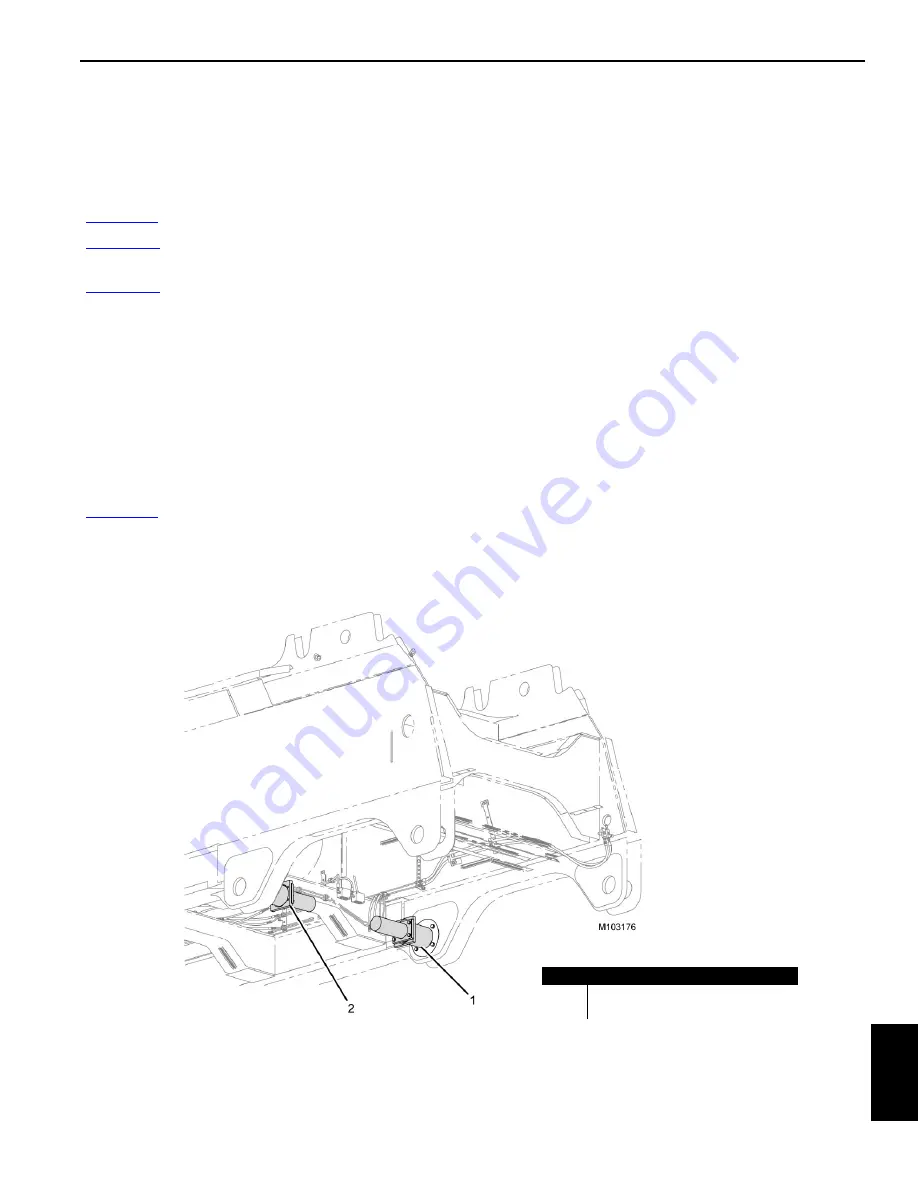
Item
Description
1
Left Side Pin Puller Assembly
2
Right Side Pin Puller Assembly
FIGURE 10-4
Содержание MLC650
Страница 1: ...R e f e r e n c e O n l y Service Maintenance Manual Manitowoc MLC650 ...
Страница 2: ...R e f e r e n c e O n l y ...
Страница 4: ...R e f e r e n c e O n l y THE ORIGINAL LANGUAGE OF THIS PUBLICATION IS ENGLISH ...
Страница 375: ...R e f e r e n c e O n l y ...
Страница 376: ...R e f e r e n c e O n l y ...


