


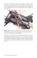


After you have the first positive lead in place, repeat the same
steps for your negative lead on the same ESC. The only thing
you should do differently is connect the lead to the negative cir-
cuit on the PDB (in our case, the right-hand strip); see Figures
.
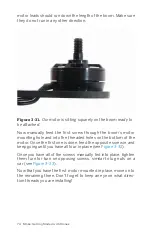
Figure 3-28.
Solder the negative lead in the same fashion, mak-
ing sure you connect it to the negative circuit seen here on the
strip closest to the bottom of the image.
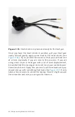
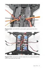
Awesome—your first ESC is connected to the PDB! Now do the
rest in the same manner (see
). Take your time and
think about where you will position the wires for all of the ESCs.
Don’t make the mistake of cutting one of your wires too short in
an attempt to save space. It’s better to leave a little extra length
at first.
70 Make: Getting Started with Drones
Содержание Belinda Kilby
Страница 1: ......
Страница 3: ...Make Getting Started with Drones Terry Kilby and Belinda Kilby...
Страница 25: ...Figure 1 5 Basic quadcopter showing how the stick commands would move the craft Introduction 13...
Страница 26: ......
Страница 90: ......
Страница 126: ......
Страница 142: ...Figure 8 7 Mobius camera next to the quick release camera mount 130 Make Getting Started with Drones...
Страница 146: ...Figure 9 4 Firmware upload has begun Figure 9 5 Firmware verification in progress 134 Make Getting Started with Drones...
Страница 153: ...Figure 9 10 Compass setup Figure 9 11 Compass calibration ArduPilot Mega APM Setup 141...
Страница 198: ......


