D i g i t a l 8 • B u s
16
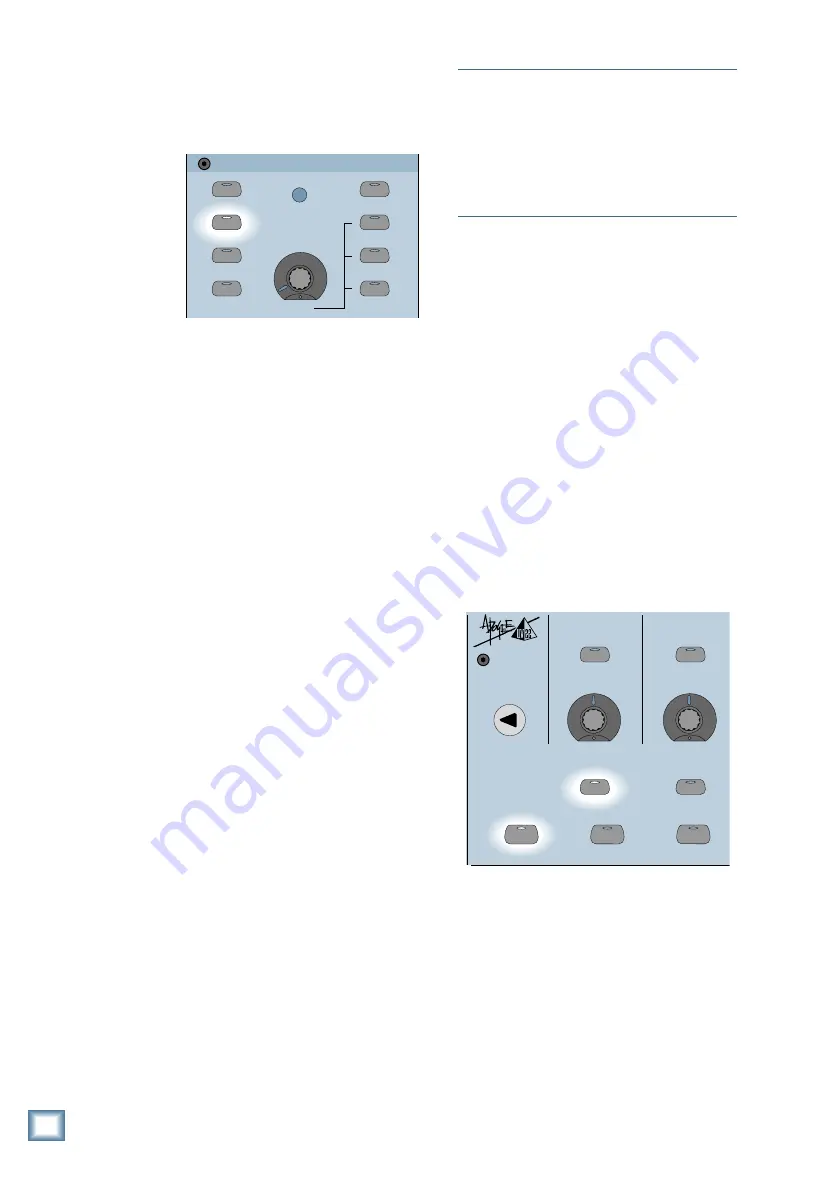
6. Press the PFL SOLO button in the
STUDIO/SOLO section. In this mode the
faders do not affect the solo level at the
Control Room output.
STUDIO/SOLO
SOLO LEVEL
STUDIO LEVEL
CLEAR SOLO
TALKBACK TO
STUDIO
AFL SOLO
PFL SOLO
MIXDOWN SOLO
TALKBACK LEVEL
LEVEL
RUDE SOLO
LIGHT
7. Press the channel SOLO button. The LED
in the button lights.
8. Make appropriate “noise” into the channel
input. For example, have a performer play/
sing/strike something or someone, etc. at
the level they’re going to record or perform.
Don’t just play a single sustained note, but
rather, jam away as you would during a
recording or performance. If the channel is
being used for a tape input during
mixdown, roll an already-recorded track
from your recorder.
9. Adjust the TRIM control. The goal is to
get the channel meter reading at or around
–15. The peaks should regularly hit, and
occasionally exceed, the –15 designation
on the meter. This is equivalent to a
+4 dBu analog level, and provides plenty
of headroom for transient peaks before
reaching 0 dB FS.
To monitor the signal, press SOLO LEVEL
in the Studio/Solo Section and adjust the
LEVEL V-Pot. Make sure the SPEAKER
LEVEL V-Pot in the Control Room Section
is turned up.
10. If desired, press the channel’s SELECT
button and adjust the EQ in the Fat
Channel (see “Using Internal Channel
Processing and Internal Effects” in the
next section). You may need to readjust the
channel’s TRIM control after changing the
EQ setting.
11. Repeat steps 5–10 on the next channel
that is being used.
12. Once you’ve achieved the proper input
sensitivity settings using this method,
clear all soloed channels and monitor the
mix in the Control Room outputs (with all
channels assigned to the L-R bus, and L-R
selected as the Control Room source) or
the Main L-R Output. Slowly bring up the
Master L-R fader to a comfortable listening
level and use the channel faders to adjust
individual levels. Leave the TRIM controls
alone. This will give you the best signal-to-
noise ratio in your mix.
General Guidelines
Note:
If you use the built-in compressor on any
channels, you can get away with turning the
TRIM control up a little higher, since the
compressor will reduce the chance of transient
peaks reaching digital clipping. Of course, the
tradeoff is that you will lose some dynamic
range (see “Using The Compressor” in Chapter
6 of the Digital 8•Bus Owner’s Manual).
Using Internal Channel Processing
and Internal Effects
Every channel on the Digital 8•Bus has its
own individual 4-band parametric EQ,
compressor, and gate. In fact, each channel can
store two separate settings for the EQ,
compressor, and gate. Want more? You can
dynamically automate the settings for the EQ,
compressor, and gate referenced to time code,
using the built-in Mackie Real Time OS
Automation software.
EQ
When you press a channel’s SELECT button,
its channel number appears in the CHANNEL
SELECT display, and its EQ settings appear in
the Fat Channel Display. If they don’t, make
sure the EQ button in the Fat Channel Section
is lit. Also make sure the ON button is lit.
ON
LOW
PREVIOUS
SELECT
LOW MID
EQ
COMPRESSOR
GATE
SETUP
SELECT
SUPER CD ENCODING
• You can toggle through the parameters
(gain, frequency, Q) for each band by
pressing the SELECT button under each
parameter in the Fat Channel Display.
• You can adjust a parameter’s value by
turning the V-Pot below each parameter.
• The EQ settings are stored in MEMORY A.
Press the MEMORY B button to create a
different EQ curve. Now you can quickly
switch back and forth between the two EQ
settings to compare how they sound, or to
make a deliberate change to the sound of
the instrument or voice in real time.


