Q u i c k S t a r t G u i d e
23
15. Roll the tape. Make sure the lead vocal
track is turned up and center-panned
between the left and right sides.
16. Click on the EFFECTS button in the Bank
Select Section to select Fader Bank 3.
SHIFT
MASTERS
1
-
24
25
-
48
49
-
72
(TRACK)
(MONITOR)
BANK SELECT
EFFECTS
MIC/LINE
TAPE IN
17. Make sure FX1–4 are assigned to the L-R
bus. Click and drag the FX1 fader up to hear
the Baritone harmony. You can pan it to the
left by clicking on PAN in the Master V-Pot
Section and then clicking and dragging the
FX1 V-Pot fully counterclockwise.
18. Click and drag the FX2 fader up to hear
the Mezzo harmony. You can pan it to the
right by clicking and dragging its V-Pot
fully clockwise.
19. Click and drag the FX3 and FX4 faders up
to hear the reverb effect on all three parts.
There are several other control modes
available in the IVL Vocal Studio. Manual Mode
and SmartChord Mode require a MIDI input
from a keyboard or sequencer to operate. Pitch
Shift Mode allows you to set a chromatic
interval between the lead vocal and the
harmony voices to create true parallel
harmonies. In addition, there is another
operating mode called Pitch Correct, which you
can use to fix out-of-tune vocal parts. More
information is provided in Appendix E in the
Digital 8•Bus Owner’s Manual, and in the IVL
Vocal Studio Owner’s Manual which you
receive when you purchase the IVL Vocal
Studio software.
Using External Effects
We’ve built in the most common effects
packages that you’re likely to use for
recording, post-production, or live sound
purposes. However, some people have favorite
effects boxes that they like to use, perhaps
even to produce a signature sound. The use of
external effects is straightforward.
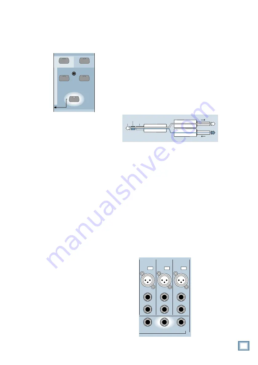
If you want to apply an external analog or
digital effect to only one channel, use the INSERT
jacks for channels 1–12 (only). This is a TRS
jack specially configured as a combination
analog Send/Return connection point (Tip =
Send, Ring = Return, Sleeve = Ground). With
nothing plugged into the INSERT jack, the
send signal is directly connected to the return
pin via the normalling jack.
• The Insert Send signal comes after the
Mic/Line preamp and TRIM control, and just
before the analog-to-digital converter.
• Connect the Send signal to the input jack of
the external processor.
• Connect the output from the external
processor to the Return connection of the
INSERT jack.
If you want to route a number of channels to
a single external effect, use an aux send. The
Digital 8•Bus has a total of 12 aux sends that
can be used for effects or monitors. The first
eight aux sends are routed to the internal
effects cards as well as the AUX OUT jacks.
You can use an internal effect and its
corresponding aux send simultaneously.
However, you can choose not to use an internal
effect by leaving its associated FX Return
control (Fader Bank 3) turned down (or turn
the PLUG-INS off in the Fat Channel). The Aux
Send on the rear panel can always be used to
send a signal to an external effect.
As an example, let’s say you want to use
Aux 2 as a send to an external digital delay.
• Connect AUX 2 on the rear panel of the
Digital 8•Bus to the input of the external
digital delay.
AUX
1
AUX
2
AUX
3
+48V
PH
+48V
PH
+48V
PH
LINE IN
INSERT
LINE IN
INSERT
LINE IN
INSERT
3
MIC
2
MIC
1
MIC
“tip”
This plug connects to one of the
mixer’s Channel Insert jacks.
“ring”
tip
ring
sleeve
SEND to processor
RETURN from processor
(TRS plug)
General Guidelines


