background image

Torchmate 2x2 Growth Series

60

Intelligent AVHC 

 for plasma

•  Approximately 95% of Growth Series customers use their equipment for cutting metal plate 

and this number seems to be growing. With this in mind, the Growth Series CNC tables with 

Accumove2 Technology come with an advanced system for achieving high quality cutting, 

with intelligent Arc Voltage Height Control.

•  The details of the Intelligent AVHC will be discussed in the next section.

Other tooling 

options

Cutting tools for Growth Series

 tables

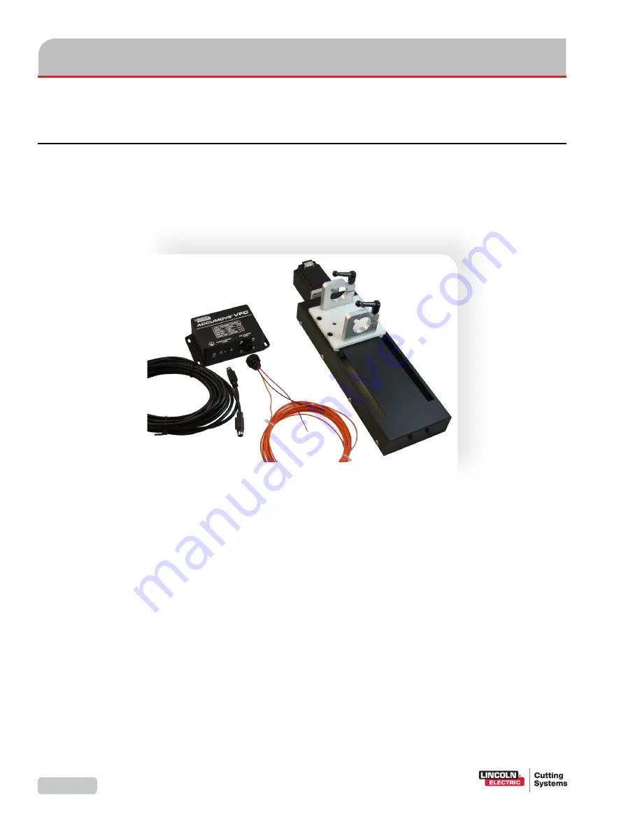
The Growth Series tables with Accumove2 Technology include an AVHC control and Z-axis lifter station for 

plasma cutting. The steps that follow illustrate the mounting and wiring for a plasma cutter and AVHC. It is 

optional to use a variety of different types of tools to preform other CNC cutting or engraving operations. 

For instructions on how to mount and configure other tool options, refer to the manuals supplied with them.

Intelligent AVHC 

 components

•  There are a number of tooling options that can be added to the Growth Series CNC tables, 

so that you can increase the versatility of your machine. 

•  Some of these options can be mounted at the same time as the plasma AVHC, but others 

cannot. Consult with your sales representative to review the options that best suit your 

needs.

•  Each of the other tooling options includes detailed instructions on how to mount and 

configure that option for use on your Growth Series table. If you have purchased one of 

these options, refer to the included Installation Guide during installation.

•  As always, if you have any difficulties, please call Torchmate Technical Support.

Содержание Growth Series

Страница 1: ...TMS 011 0204 02 GROWTH SERIES GROWTH SERIES with ACCUMOVE 2 Technology Assembly Guide GROWTH SERIES GROWTH SERIES Torchmate 2X4 Growth Series May 14 2015 Copyright 2012 2015 by Torchmate Inc ...

Страница 2: ...ing Systems All rights reserved Reproduction of this work in whole or in part without written permission of the publisher is prohibited The publisher does not assume and hereby disclaims any liability to any party for any loss or damage caused by any error or omission in this manual whether such error results from negligence accident or any other cause Publication Date May 2015 Document TMS 011 02...

Страница 3: ...Assembly Guide iii 2X4 Growth Series CNC Cutting Table pictured with optional water table and plasma torch GROWTH SERIES GROWTH SERIES ...

Страница 4: ...k adjust vertical bearings 29 Step A5 Adjust the first cross member 30 Step A6 Adjust the second cross member 31 Step A7 Link the gantry to the drive screws 32 Binding the Accumove 2 33 Overview of wiring 34 Step B1 Run crossover Ethernet cable 35 Step B2 Run motor cables 36 Step B3 Install the VMD software 37 Step B4 Set the IP address 38 Step B5 Set the initial datum and log on to VMD 39 Step B6...

Страница 5: ... slats 57 Step C8 Secure cutting table to water table 58 Deploying the Plasma Cutter 59 Cutting tools for Growth Series tables 60 Features of the Accumove2 AVHC 62 Step D1 Attach the tool mounting bracket to the tool mounting pate 64 Step D2 Mount the AVHC lifter 66 Step D3 Prepare the plasma cutter 68 Step D4 Place the VFC unit 70 Step D5 Connect the VFC unit 72 Step D6a Wiring for Lincoln Electr...

Страница 6: ... If any of the warranted items are found by Seller to be defective such Goods will at Seller s option be replaced or repaired at Seller s cost No defective goods are to be returned without written authorization of seller The sole purpose of the stipulated exclusive remedy shall be to provide the Buyer with free repair and replacement of defective Goods in the manner provided herein This exclusive ...

Страница 7: ...ten notice of any claim for shortage overcharge or damage of Goods within ten 10 days from invoice date such Goods shall be deemed finally inspected checked and accepted by Buyer and no allowances shall be made thereafter In absence of shipping and packaging instructions Seller shall use its own discretion in the choice of carrier and method of packing Seller shall not be responsible for insuring ...

Страница 8: ... of it what you put in Operating any machinery is a skill and does have a learning curve The first and perhaps most important item we want to give you today is the Torchmate Technical Support Hotline 866 571 1066 This number is toll free for those within the United States For those outside the United States use the following telephone number 775 673 2200 There is a dedicated professional support s...

Страница 9: ...Torchmate tables brought major cost reductions allowing plasma cutting which had been expensively out of reach for most shops to be widely affordable The cut quality increased production and precise replication were also highly appreciated capabilities of the new machines In early 2001 and with the help of Kunz s son Bill Jr the company unveiled the Torchmate 2 which used an extruded aluminum gant...

Страница 10: ... or a part is missing please contact Torchmate technical support Technical support will also help you with operating the CNC system and troubleshooting problems Torchmate Technical support is available Monday through Friday from 6 AM to 4 PM 06 00 to 16 00 Pacific Time Zone Call Fax or Email Technical Support Call us for Consumables or visit our web store www TorchmateStore com ...

Страница 11: ...Assembly Guide 1 Safety Information ...

Страница 12: ...t or gouged to a good electrical earth ground 1 6 Maintain the plasma torch cable and work clamp in good safe operating condition Repair or replace all worn or damaged parts Replace damaged insulation 1 7 Never dip the torch in water for cooling or plasma cut or gouge in or under water 1 8 When working above floor level protect yourself from a fall should you get a shock 1 9 Operate the pilot arc ...

Страница 13: ...able non flammable screening and or warn them not to watch the arc nor expose themselves to the arc rays or to hot spatter or metal 3 FUMES AND GASES can be dangerous 3 1 Plasma cutting or gouging may produce fumes and gases hazardous to health Avoid breathing these fumes and gases When cutting or gouging keep your head out of the fumes Use enough ventilation and or exhaust at the arc to keep fume...

Страница 14: ...uctions for this equipment and follow your employer s safety practices 3 9 This product when used for cutting produces fumes or gases which contain chemicals known to the State of California to cause birth defects 3 10 Some dust created by routing sawing grinding drilling and other construction activities contains chemicals known to cause cancer birth defects or other reproductive harm Avoid prolo...

Страница 15: ... gouging area as practical Work cables connected to the building framework or other locations away from the cutting or gouging area increase the possibility of the current passing through lifting chains crane cables or other alternate circuits This can create fire hazards or overheat lifting chains or cables until they fail 4 7 Hydrogen gas may be formed and trapped under aluminum work pieces when...

Страница 16: ...dations 7 PLASMA ARC can injure 7 1 Keep your body away from nozzle and plasma arc 7 2 Operate the pilot arc with caution The pilot arc is capable of burning the operator others or even piercing safety clothing 8 ELECTRIC AND MAGNETIC FIELDS may be dangerous 8 1 Electric current flowing through any conductor causes localized Electric and Magnetic Fields EMF Cutting or gouging current creates EMF f...

Страница 17: ...0 1 1 To protect your hearing from loud noise wear protective ear plugs and or ear muffs Protect others in the workplace 10 1 2 Noise levels should be measured to be sure the decibels sound do not exceed safe levels 10 2 For information on how to test for noise refer to the publications section of this manual 11 HEAVY PARTS 11 1 Parts of CNC machines are heavy Also material you are cutting may be ...

Страница 18: ...00 C Any parts and scrap will be very hot after cutting Use extreme care 15 2 Use tongs and wear protective gloves when handling recently cut material Also consider other devices for safe hot material handling 15 3 It is safest to let material cool completely before handling 16 MECHANICAL DRIVES 16 1 High speed mechanical drives made of gears belts and or drive screws are used by CNC machines Keep...

Страница 19: ...ble from American Welding Society 550 N W LeJeune Rd Miami FL 33126 NFPA Standard 51 OXYGEN FUEL GAS SYSTEMS FOR WELDING CUTTING AND ALLIED PROCESSES obtainable from the National Fire Protection Association Batterymarch Park Quincy MA 02269 NFPA Standard 70 NATIONAL ELECTRICAL CODE obtainable from the National Fire Protection Association Batterymarch Park Quincy MA 02269 NFPA Standard 51B CUTTING ...

Страница 20: ...ern arises or a part seems to be missing please contact Torchmate technical support Technical support will also help you with operating the CNC system and troubleshooting problems Torchmate technical support is available Monday through Friday from 6 AM to 4 PM 06 00 to 16 00 Pacific Time Zone Call fax or email Technical Support Call us for Consumables or visit our web store www TorchmateStore com ...

Страница 21: ...Assembly Guide 11 Receiving and Preparation ...

Страница 22: ... efficiency Consider placing the equipment in an area that can handle any expansion as needed The following components of the system must be supplied with power CNC Control box Plasma power supply separate purchase Computer separate purchase Air compressor separate purchase Oxyfuel plate marker relay box optional Always consult with your electrical service provider or a qualified electrician to en...

Страница 23: ...an to remove it and to provide a supply of clean air Consumables If you know the types of materials and the thicknesses you will be cutting you can plan to keep a good stock of consumables on hand This will avoid machine downtime and the scramble to obtain replacement consumables on short notice To order consumables just call Torchmate Parts Support or visit our store website The Lincoln Electric ...

Страница 24: ...ly inspect your shipment Look for dented bent or broken parts Immediately contact Torchmate Technical Support if any damage is found The crate containing the cutting table components weighs about 315 lbs The optional crate containing the water table components weighs about 290 lbs Take care to observe safety procedures when moving and unpacking these crates Check that all parts have arrived and th...

Страница 25: ...inum cross member 2 Wide GS TMS 180 0002 08 A2 1 GS 2 gantry assembled TMS 180 1000 01 A3 4 Screw BSCS 3 8 16 X 1 2 TMS 410 0318 08 A6 Parts for the A steps On the next few pages the parts included in your Torchmate 2X4 Growth Series CNC Cutting System ship ment are listed in the order you assemble them To make it easier to complete the assembly of your cutting system you can lay out the received ...

Страница 26: ...ble red 5 ft TMS 103 5000 07 B1 1 Laptop or PC with Microsoft Windows 8 Windows 7 Vista or XP separate purchase B1 3 Cable motor XLR Molex 25 ft TMS 402 0010 01 B2 1 USB flash drive VMD software and owners manuals TMS 100 1000 01 B3 4 99R6 ball bearings TMS 432 0010 01 B9 4 Screw BSCS 3 8 16 X 1 TMS 410 0218 16 B9 4 Nut Nylock 3 8 16 steel zinc plated TMS 414 0201 18 B9 16 Washer flat 3 8 steel ca...

Страница 27: ...leg side leg TMS 180 0001 29 C2 6 3 8 16 stud leveling foot TMS 448 0001 01 C2 69 Screw BSCS 5 16 18 X 5 8 TMS 410 0216 10 C3 C4 C5 69 Nut Nylock hex 5 16 18 steel zinc plated TMS 414 0201 16 C3 C4 C5 2 GS water table side long TMS 180 0001 07 C4 2 GS water table side short TMS 180 0001 08 C4 1 GS water table cross member 30 TMS 180 0005 01 C5 1 GS Water pan 2X2 TMS 180 0002 02 C6 1 GS water pan 2...

Страница 28: ...12 C8 4 Washer flat 1 4 washer steel zinc plated TMS 413 0001 16 C8 Parts for the C steps continued optional Qty Part Description Part Number Step 1 Tooling bracket Accumove2 lifter TMS 180 0150 02 D1 2 D1 2 D1 1 Height Control Lifter Accumove2 TMS 101 1100 02 D2 4 Screw SCS 5 16 18 X 1 0 lg hex drive TMS 410 0016 16 D2 1 Plasma cutter power supply unit Purchased separately D3 1 CNC Interface cabl...

Страница 29: ...on Part Number Step 1 Height control cable TMS 103 5000 01 D5 1 Chassis ground wire From your toolbox D5 1 Ohmic Cap torch consumable stack Depends on plasma power unit D5 1 Raw arc voltage cable included with CNC Interface cable for Lincoln Electric plasma power units Depends on plasma power unit D5 1 Quick connect crimp terminal female From your toolbox D5 1 Terminal Block Plug 2Pos Str 5 08mm T...

Страница 30: ...the first set of adjustments B steps Binding the cutting table to the Accumove2 CNC controller This involves Establishing communication Connecting the motor cables Installing the VMD software Using the controller dynamically to adjust the table to get it square and tight C steps Coupling the cutting table to the water table optional is next In addition to providing support for the workpiece being ...

Страница 31: ...e Monday through Friday from 6 AM to 4 PM 06 00 to 16 00 Pacific Time Zone Written instructions Detailed instructions are provided for each assembly step If you ever find the instructions unclear please contact Torchmate Technical Support and let us know so that we can not only give you immediate assistance but so that we can also make improvements to the instructions For each step in the assembly...

Страница 32: ... or a part is missing please contact Torchmate Technical Support Technical Support will also help you with operating the CNC system and troubleshooting problems Torchmate Technical Support is available Monday through Friday from 6 AM to 4 PM 06 00 to 16 00 Pacific Time Zone Call Fax or Email Technical Support Call us for Consumables or visit our web store www TorchmateStore com ...

Страница 33: ...Assembly Guide 23 Assembling the cutting table ...

Страница 34: ...assembly steps The cutting table is assembled in a series of easy A steps Step A1 Prepare the table sides Step A2 Assemble the table frame Step A3 Install the gantry Step A4 Check adjust vertical bearings Step A5 Adjust the first cross member Step A6 Adjust the second cross member Step A7 Link the gantry to the drive screws The B steps follow and bind the controller to the cutting table allowing f...

Страница 35: ... in the water table reservoir After being removed from the crate the combined weight is 280 lbs 125 kg before adding water Whether full or empty of water do NOT drag the cutting table when moving it to a new location If you drag the CNC cutting table water table you can damage it and get it out of square Do NOT try to move the cutting table without help When you must re position the CNC cutting ta...

Страница 36: ... members Qty Part Description Part 1 GS 4 side set assembled L R set TMS 180 1000 05 12 Screw BSCS 5 16 18 X 7 8 T bolt TMS 410 0216 14 12 T nut 5 16 18 steel black plated TMS 414 3101 16 Required parts components Instructions Illustration On each end of each pre assembled side insert three 5 16 18 X 5 8 button head screws through the holes from the outside Fasten a 5 16 18 T nut to each screw Lea...

Страница 37: ...ss members The final adjustment for squareness is completed at a later step Required parts components Instructions Illustration Perform this assembly on a flat level surface Slide the cross members onto the T nuts on the pre assembled sides There are channels in the extruded aluminum cross members for the T nuts to slide into When the T nuts are tightened they will hold table securely The T nuts w...

Страница 38: ...Part 1 GS 2 gantry assembled TMS 180 1000 01 1 Assembled frame components From Step A2 Required parts components Instructions Illustration Loosen the inner and outer bearings so that they can be moved outward to give clearance for the rail Set the gantry onto the sides over the rails Make sure the vertical bearings are taking the weight of the gantry and that it is free to move Ensure that the gan...

Страница 39: ...table From Step A3 Required parts components Measure the front and back clearances between each gantry end and the rails four total measurements A clearance of approximately 1 8 is desired Hint The thickness of a new penny and a new dime 0 114 in or two new pennies 0 122 in is a good beginning clearance Loosen and adjust each vertical bearing as necessary to achieve an equal clearance of approxima...

Страница 40: ...ackets Align the bracket holes with the gantry holes If there is a gap between the bracket and the gantry slide the sides outward in the cross member channel until the gantry and bracket just touch with no pressure If there is tightness between the bracket and the gantry slide the sides inward in the cross member channel until the gantry and bracket just touch with no pressure Tighten one of the T...

Страница 41: ...parts components Instructions Illustration First measure here outside of rail to outside of rail Second measure here Adjust this end s rail spacing to make both measurements equal Measure the distance between the outside edges of the rails at the gantry end Measure the distance between the outside edges of the rails at the other non gantry end Adjust side rails in the cross members at the other no...

Страница 42: ...uctions Illustration Check that you can bolt the gantry to the aluminum bracket without applying vertical force If the holes do not align vertically adjust the gantry clearance by re positioning the vertical bearings The bearings should support the entire weight of the gantry leaving the drive screw free to rotate without any binding Attach the gantry to the aluminum anti backlash drive screw brac...

Страница 43: ...Assembly Guide 33 Binding the Accumove 2 ...

Страница 44: ...The Accumove2 controller is the destination for the table s motor cables and the computer s Ethernet crossover cable The cable ends are ready to plug in to the back of the box The Accumove2 box should be located so that it is not exposed to cutting spatter or splashing from a water table and so that the motor cables do not need to be coiled Coiled cables can introduce troublesome noise into the el...

Страница 45: ...the connectors Be sure to use the red crossover Ethernet cable to connect directly from the computer to the Accumove2 CNC controller Run the red crossover cable from the computer s Ethernet port to the active right hand port on the Accumove2 CNC controller box The left hand port is inactive for connecting to the laptop or PC Required parts components Instructions Qty Part Description Part 1 Accumo...

Страница 46: ... Ethernet Crossover Cable Connect the motors to the Compact CNC Controller box with the 25 ft motor cables They have color coded ends and should be connected as illustrated The purple color coded wire for the Z axis torch lifter motor will be connected in part D The cables should click into place To avoid electronic noise be careful not to crimp the wire especially near the connectors at either en...

Страница 47: ...copies the software onto your computer and continues the installation To complete the installation click the radio button that accepts the End User License Agreement EULA Under Customer Information enter a User Name and Organization then click Next For the Destination Location accept the default and click Next When the installer completes click the Finish button The program s icon will be in the o...

Страница 48: ...k Connections window disable all connections except for the wired crossover cable connection by right clicking on the icon s and selecting Disable Right click on the crossover connection and select Properties Select Internet protocol version 4 TCP IPv4 Select the Properties button below the list Select Use the following IP address Enter 192 168 1 6 in the IP address field Press the Tab key to fill...

Страница 49: ...se irreversible damage to the Accumove2 If you haven t powered on the Accumove2 and started the VMD software perform these steps Until the Accumove2 completes its start up process you may see a Not Connected screen which should soon disappear A notice box requests Please switch the drives on Click Hide The drives are automatically switched on when the table Datum is set in a later step Click the L...

Страница 50: ...lay the Configuration control panel then click the Load Configuration button Select the your machine s configuration file and click OK Unless your table is reconfigured you will not need to change any of the settings When you install the VMD software the standard configuration files for Torchmate tables are placed in the C Torchmate Controller Data Configurations folder After any custom configurat...

Страница 51: ...he datum Click the Datum button to enable the jog buttons If the table s gantry is not already at the table s zero X position limit it will need to be jogged there At this point in the setup and adjustment of the table the tool s Y position on the gantry is not critical but jogging to the table s zero Y position limit is good practice Accumove2 is designed to operate in the X Y quadrant For safety...

Страница 52: ...on Datum the table and load the correct configuration file See Step B6 and B7 Click the Home button Click the Job Setup button Click the Y and Y arrow buttons to move the gantry from one end of the table to the other As the bearings have not been tightened they will self adjust during the movement Use the jog Arrow buttons to move the gantry to the other end of the table The arrows are sensitive t...

Страница 53: ...installing underside roller bearings The top and side bearings are pre installed on the gantry but you must add the underside bearings for routing configurations For use in routing applications assemble four roller bearings on the underside of the gantry two on each side Each assembly includes a button head screw four washers a roller bearing and a hex nut Pass the screw through one washer then th...

Страница 54: ...he Job Setup button Click the Y and Y buttons to move the gantry from one end of the table to the other Because the side bearings have not been tightened down they should adjust their position during the movement The gantry should move freely If so tighten the bearing nuts maintaining and re checking the bearing positions Select Fast jogging speed by clicking the arrow and dragging toward the arro...

Страница 55: ...ct the height control cable between the VFC unit and the Accumove2 Connect the torch relay wires in the plasma cutter s CNC cable to the Accumove2 Make the connections from the plasma cutter s CNC cable to the VFC unit and also to the Accumove2 Connect ground wires to the VFC unit and to the Accumove2 Run the torch lead from the plasma cutter to the gantry torch mount Keep the torch lead as far as...

Страница 56: ...Torchmate Growth Series 46 ...

Страница 57: ...Assembly Guide 47 Coupling the water table optional ...

Страница 58: ...ect the end panel with legs to the side panels Step C5 Seal the water pan edge to the water pan bed Step C6 Install the drain valve and place the pan within the table Step C7 Add the material support slats Note these slats are components you will cut to fit from local material and are not included in your shipment Step C8 Secure the cutting table to the water table Required space The completed wat...

Страница 59: ...ty so that it can safely support the material you cut With the cutting table installed the table is even heavier close to 280 lbs 127 kg To prevent damage to the table and to maintain its square alignment never drag it When you need to re position the water table or move it to a new location drain all the water and get help lifting it ...

Страница 60: ...ents Instructions Illustration Qty Part Description Part 2 GS water table side long with cutout TMS 180 0001 05 2 GS water table side backplate long TMS 180 0001 06 12 Screw BSCS 10 32 X 1 2 TMS 410 0511 08 12 Nut Nylock 10 32 steel zinc plated TMS 414 0201 11 Attach the Side Panel Back Plate to the Torchmate Cut Side using six 10 32 Button Head Cap Screws and six 10 32 Hex Nuts Repeat this assemb...

Страница 61: ...able assembly is to attach a leveling foot to each of the four legs The leveling feet are used to level the table when the floor is uneven Each leg will be adjusted individually before filing the table with water Required parts components Instructions Illustration On each Corner Leg attach one 3 8 Leveling Foot into the bottom base plate Repeat for each side leg The leveling feet will be adjusted ...

Страница 62: ...nd panel component From Step C1 4 Assembled corner leg component From Step C2 12 Screw BSCS 5 16 18 X 5 8 TMS 410 0216 10 12 Nut Nylock hex 5 16 18 steel zinc plated TMS 414 0201 16 Attach one assembled cut out side from Step 1 to two assembled legs from Step 2 using six 5 16 18 x 5 8 Button Head Cap Screws and six 5 16 18 Hex Nuts The side panels are slotted to be adjusted once the cutting table ...

Страница 63: ...414 0201 16 Step C4 Connect the side legs and side panels In the fourth step you will attach the side legs and panels to the corner legs and end panel assemblies Be cause adjustments may be required you ll only partly tighten the screws Complete assembly of the legs and sides of the water table frame Attach the side panels short and long to the side legs and end panel corner leg components using 5...

Страница 64: ... Assembled panel and leg components From Step C4 1 GS water table cross member 30 TMS 180 0005 01 Insert the cross member into the support channels welded into the side legs These will support the cross member and the weight it carries No attaching hardware is required Note the slotted side panels will be adjusted after the cutting table is place upon the water table Do not fully tighten the cap s...

Страница 65: ... 410 0216 10 35 Nut Nylock hex 5 16 18 steel zinc plated TMS 414 0201 16 1 GS silicone sealant tube TMS 180 1001 01 Apply a generous continuous double bead of silicone sealant to the mating surfaces of the water pan beds and edge Avoid gaps in the sealant which may cause leakage Attach the water pans together and then add the edge with screws and nuts Don t tighten so much as to squeeze out all th...

Страница 66: ...d water pan From Step C6 1 TFP AR small table 3 4 plumbing water release valve TMS 459 0010 01 1 PTFE thread sealant tape recommended separate purchase Wrap PTFE tape around the valve threads and tighten the water release valve into the water pan Get some help as the pan is heavy Carefully lower the pan into the table frame assembled in Step 5 The pan simply rests in the frame You may connect a ho...

Страница 67: ... Assembled water table with pan From Step C7 19 Material support slats 301 2 x 3 to 4 x 3 16 Obtain slats locally not supplied Cut nineteen material support slats from 3 16 thickness material Make them 301 2 long and between 3 and 4 wide This material is not supplied with your water table 3 to 4 high slats may be used A 4 high slat will place the material at the top of the water table A lower slat...

Страница 68: ...escription Part 1 Cutting table From Step A14 1 Water Table From Step C8 4 Screw BSCS 1 4 20 X 3 4 TMS 410 0214 12 4 Washer flat 1 4 washer steel zinc plated TMS 413 0001 16 Attach the cutting table to the water table s legs The legs have threaded holes Use button head cap screws and flat washers Check that the table is square and level Adjust the leveling feet as needed Refer to Step A5 of the cu...

Страница 69: ...Assembly Guide 59 Deploying the Plasma Cutter ...

Страница 70: ... AVHC It is optional to use a variety of different types of tools to preform other CNC cutting or engraving operations For instructions on how to mount and configure other tool options refer to the manuals supplied with them Intelligent AVHC components There are a number of tooling options that can be added to the Growth Series CNC tables so that you can increase the versatility of your machine So...

Страница 71: ...rmation about the availability of dual tool mounting Review the installation manual that comes with the plate marker for detailed instructions With special optional mounting adapters an oxy fuel torch may be installed upon your Growth Series CNC table to facilitate cutting heavier plate than plasma can cut Review the installation manual that comes with the oxy fuel torch for detailed instructions ...

Страница 72: ...ng speed for a given arc length and amperage Using sophisticated computations the Accumove2 adjusts the speed and torch height at various points along curves and at corners to compensate for the changes in effective arc length that happen in those parts of the cuts to achieve greater quality and reliability Before an arc is initiated by the Accumove the AVHC must raise the torch tip to the recomme...

Страница 73: ...For more information on what you can do to reduce EMI effects and ensure the highest cut quality for your Growth Series with Accumove2 Technology CNC system please find the file EMI Reduction pdf on the Torchmate Lincoln Electric Cutting Systems USB Flash Drive supplied with your system or download it from this web location http www torchmatesupport com help EMI Reduction zip A magnetic breakaway ...

Страница 74: ...angle tool mounting plate Qty Part Description Part 1 Motor Cables Ethernet Crossover Cable Laptop or PC Accumove2 and wired CNC Cutting table From Step B10 1 2 2 Required parts components The standard tool mounting plate is attached to the gantry To mount the tool mounting bracket to the plate follow these steps Remove the tool mounting plate from the gantry Use the 4 screws and nuts to attach th...

Страница 75: ...e Use of the tool mounting bracket is only required if the full 24 of travel is required on the Y axis The plasma height control Z axis may be attached directly to the tool mounting plate Approximately 1 4 is lost in Y axis travel along the rails by direct mounting leaving approximately 233 4 of travel Slighly more than 1 is lost in Y axis travel by direct mounting if the optional magnetic breakaw...

Страница 76: ... it supports a tool mounting bracket To mount the AVHC Z axis lifter to the tool mounting bracket Insert the 4 screws through the back of the bracket and into the threaded holes in the back of the lifter station There is adjustment available for the height in the lifter station slots Mount the Z axis lifter station as high above the cutting surface as possible To mount the AVHC Z axis lifter to th...

Страница 77: ...mounting bracket or tool mounting plate Run the cables for the torch power z axis motor the ohmic cap and the optional magnetic breakaway using the cable carrier You may help reduce EMI effects by separating the motor signal cables from the torch power cables by running the torch power cable on the outside of the cable carriers Connect the cables Use cable ties to run the torch power cable outside...

Страница 78: ...Supplied with plasma cutter Required parts components Making wire splices to the CNC cable and other cables 20 gauge twist on wire nut connectors typically gray or blue Crimp on butt splice connectors be sure to use the proper size connector and the proper crimping tool Solder joints with shrink wrap Wire nut Butt splice Solder joint If the CNC cable ends have lug connectors clip these connectors ...

Страница 79: ... raw arc voltage for controlling the torch height This cable simplifies wiring for the Accumove2 For other plasma power units the raw arc voltage signal is frequently not available on the CNC cable If you purchased one of these units with your Torchmate Growth Series CNC System the factory will have installed the necessary raw arc voltage cable before shipping If your plasma power unit was not par...

Страница 80: ...ch tip Height control cable connector connects to the Accumove2 Ground wire screw terminal The enclosure has mounting flanges and 4 holes for mounting Select a suitable location for mounting the Accumove VFC unit It should be close to the plasma power unit to keep the raw arc voltage wires short The benefit of this is it reduces EMI problems EMI is an important consideration for producing high qua...

Страница 81: ...m the CNC interface cable VFC Shorter distance Height control cable Longer distance CNC interface cable VFC Shorter distance CNC interface cable Longer distance Height control cable To reduce the length of the raw arc voltage wires you can trim the entire CNC interface cable so that it just reaches the Accumove VFC unit ...

Страница 82: ... connector into it Accumove VFC socket Connect a ground wire to the green screw terminal Run the ground wire to the Accumove ground post Uncoil the long orange wire from the arc voltage cable connector and run this to the table through the cable carriers to the torch and Splice the red and black wires from the arc voltage cable to the arc voltage wires in the Lincoln Electric CNC interface cable r...

Страница 83: ...l port Splice the red and black wires to the plasma power unit s raw arc voltage wires Be sure to observe polarity Run the orange wire to the ohmic sensing cap using a quick connect crimp terminal Run the ground wire from the VFC to the Accumove2 ground terminal Splice and connect the cables ...

Страница 84: ...Connect the D and G cables to the VFC black and red cables Be sure to observe the correct polarity on this Raw Arc Voltage signal Run the height control cable from the VFC to the Accumove the wiring components for the control of the torch and control of the AVHC unit Both ends of this cable are the same It s best to position the VFC close to the plasma power unit and well away from the Accumove2 i...

Страница 85: ...away Longer Height Control Cable Ohmic Cap Shorter Raw Arc Voltage Cable VFC Motor Cables Start Arc Now Arc Established OK to Move SPLICE SPLICE SPLICE SPLICE SPLICE SPLICE SPLICE K M I J D G Ground Cable Use this wiring diagram for Lincoln Electric plasma cutters ...

Страница 86: ...ical Support for assistance with this step Provide the brand and model number of your plasma power unit and ask for instructions on connecting your VFC to the Raw Arc Voltage Call Monday through Friday from 6 AM to 4 PM 06 00 to 16 00 Pacific Time Zone Toll Free 1 866 571 1066 International 775 673 2200 Fax 775 673 2206 Email support torchmate com Run the height control cable from the VFC to the A...

Страница 87: ...de by Lincoln Electric 3 3 Table Motors Crossover Ethernet Mag Breakaway Longer Height Control Cable Ohmic Cap Shorter Raw Arc Voltage Cable VFC Motor Cables Start Plasma Now SPLICE OK to Move Plasma Started SPLICE SPLICE SPLICE SPLICE SPLICE SPLICE SPLICE SPLICE SPLICE ...

Страница 88: ...Torchmate 2x2 Growth Series 78 ...

Страница 89: ...Assembly Guide 79 Maintenance and Parts ...

Страница 90: ...ever be cleaned with solvent based lubricant water displacement products For proper lubrication use a light machine oil A few drops of oil on a frequent and regular basis is much better than a heavy dose only occasionally Some components such as set screws can become loose over time Every time the table is used it should be inspected before and during operation for any signs of vibration or loosen...

Страница 91: ...in regular use Use the lubricant cleaner sparingly but leave a light film on the rails to keep dust and moisture from accumulating on the rails This is particularly important in a damp or humid climate or where condensation is normally found on metal parts Avoid the use of steel wool as the fine steel fibers can come free from the pad and get inside the moving parts the electronic connectors or th...

Страница 92: ...TMS 180 0004 02 1 Anti backlash drive nut for 4 sides TMS 180 0004 05 1 60 tooth pulley TMS 180 0004 17 1 30 tooth pulley TMS 180 0004 22 1 4 side timing belt TMS 180 0004 19 1 Stepper motor NEMA 23 390 oz in XLR TMS 404 0023 06 1 Acetal flanged sleeve bearing for 3 8 shaft TMS 432 0011 01 1 Acetal thrust washer for 1 2 shaft TMS 432 0008 01 1 1 4 shaft collar TMS 433 0012 01 4 99R6 ball bearings ...

Страница 93: ...ur 2X4 table top machine TMS 041 0204 03 To grow a 2x4 table top machine to 4x4 TMS 045 0404 02 To grow a 2x2 machine with water table to 4x4 TMS 045 0404 02 and TMS 045 0404 04 For these and other growth combinations please contact the Torchmate sales offices 866 571 1066 Also spare parts and consumables can be ordered by contacting the Torchmate Support Department at the same number or by visiti...

Страница 94: ...Torchmate Growth Series 84 Toll Free 1 866 571 1066 International 775 673 2200 Fax 775 673 2206 Email support torchmate com ...

Отзывы: