Get Started
248083401-1 Rev 5
3-5
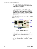
4. On the instrument end of the cable, push the end of the cable
through the large Lock Ring and RJ-45 housing as illustrated in
Figure 3-2. Make sure the Lock Ring is oriented as shown in
Figure 3-2. If it is reversed, the cable will have to be cut, the RJ-45
connector discarded and a new connector installed.
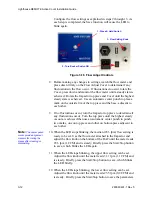
Figure 3-2 Housing with Cable Inserted
5. Strip 1-1/2-inch to two-inches of insulation from the end of the
cable, taking extreme care to not nick or cut the individual wires.
Do NOT strip the individual wires.
6. Separate the pairs of wires down to the cable’s insulation. There
will be an orange, a green, a blue and a brown pair of wires. Each
pair will have a solid color wire and one striped wire of the pair
color. Do not get them confused - the orange and brown pair may
look alike in plenum cable and “swapping” these two pairs will
cause failure of the cable.
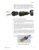
7. Carefully untwist each pair and straighten the wire. The individual
wires will be inserted into the Wire Loom shown in Figure 3-1 and
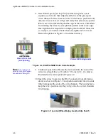
Figure 3-3. Note the Loom’s flat tray shape. Insert the wires into
the loom based on the EIA/TIA-568B standard as shown in Figure
3-4.
Figure 3-3 Close-up of Wire Loom
Cable shown
after Step 5
Note Orange/White wire
Note the Loom
orientation
Содержание REMOTE Active Count
Страница 1: ......
Страница 2: ...00...
Страница 6: ......
Страница 10: ...Lighthouse REMOTE Active Count Installation Guide ii 248083401 1 Rev 5...
Страница 12: ...Lighthouse REMOTE Active Count Operating Manual 1 2 248083401 1 Rev 5...
Страница 56: ...MODBUS Register Map v1 49 248083401 1 Rev 5 A 18...
Страница 58: ...Lighthouse REMOTE Active Count Installation Guide B 2 248083401 1 Rev 5...
Страница 61: ...00...
Страница 62: ......


