


Lighthouse REMOTE Active Count Installation Guide
3-6
248083401-1 Rev 5
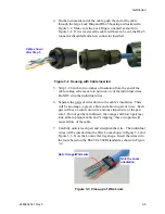
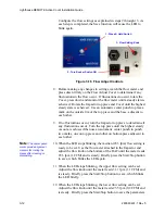
8. Note that the green pair is split up and the blue pair is out of
sequence (solid color then striped) and between the green-pair
wires. When all of the wires are in the correct holes, push the loom
onto the wires as far as it will go and verify that at least one-quarter-
inch of each wire extends beyond the edge of the loom. This allows
for trimming the wires in a straight line parallel to the loom edge.
One-eighth-inch is required for crimping into the RJ-45 connector
so, in step 9, do not trim shorter than one-eighth-inch (3.2 mm).
Review the photos in Figure 3-4 to ensure accuracy.
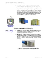
Figure 3-4 EIA/TIA-568B Color Code Example
Note:
The “pairing” of
wires in the loom changes
at positions 4 through 6.
9. Continue to push the cable into the loom and trim the ends of the
wires in a straight line to 1/8-inch to 3/16-inch (3.2 - 4.6 mm) as
illustrated in the center panel of Figure 3-4.
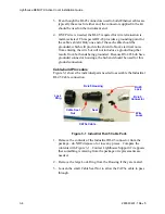
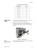
10. Insert the wires / loom into the RJ-45 connector (lock tab facing
down) as shown in Figure 3-5 and push inward until the wire ends
fully butt against the ends of the wire channels. The loom helps to
keep the wires positioned so they will go into the correct channels
for crimping.
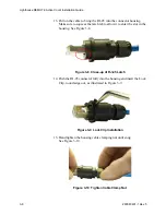
Figure 3-5 Loomed Wires Being Inserted into RJ-45
View is tab facing reader
View is from Hub
jack opening
Содержание REMOTE Active Count
Страница 1: ......
Страница 2: ...00...
Страница 6: ......
Страница 10: ...Lighthouse REMOTE Active Count Installation Guide ii 248083401 1 Rev 5...
Страница 12: ...Lighthouse REMOTE Active Count Operating Manual 1 2 248083401 1 Rev 5...
Страница 56: ...MODBUS Register Map v1 49 248083401 1 Rev 5 A 18...
Страница 58: ...Lighthouse REMOTE Active Count Installation Guide B 2 248083401 1 Rev 5...
Страница 61: ...00...
Страница 62: ......