


29
Refrigerant Piping
Due to our policy of continuous product innovation, some specifications may change without notification.
©LG Electronics U.S.A., Inc., Englewood Cliffs, NJ. All rights reserved. “LG” is a registered trademark of LG Corp.
REFRIGERANT PIPING DESIGN
System Engineering
Pipe Bends
When bending soft copper, use long radius bends. Refer to the "Radii of Coiled Expansion Loops and Developed Lengths of Expansion
Offsets” table for minimum radius specifications, page 28.
In-line Refrigeration Components
Components such as oil traps, solenoid valves, filter-dryers, sight glasses, tee fittings, and other after-market accessories are not permitted
on the refrigerant piping system between the water source units and the indoor units. Multi V Water Mini systems are provided with redun-
dant systems that assure oil is properly returned to the compressor. Sight-glasses and solenoid valves may cause vapor to form in the liquid
stream. Over time, dryers may deteriorate and introduce debris into the system. The designer and installer should verify the refrigerant pip-
ing system is free of traps, sagging pipes, sight glasses, filter dryers, etc.
Field-provided Isolation Ball Valves
LG allows the installation of field-supplied ball valves with Schrader ports at each indoor unit. Full-port isolation ball valves with Schrader
ports (positioned between valve and indoor unit) rated for use with R410A refrigerant should be used on both the liquid and vapor lines.
If valves are not installed and a single indoor unit needs to be removed or repaired, the entire system must be shut down and evacuated. If
isolation ball valves are installed, and an indoor unit needs to be repaired, the unaffected indoor units can remain operational. Reclamation
of refrigerant, then, can be restricted to a single indoor unit.
Position valves with a minimum distance of three (3) to six (6) inches of pipe on either side of the valve, and placed between six (6) and
twelve (12) inches from the Y-branch or header connecting the run-out pipe to the upstream main or branch pipe. If ball valves are installed
closer to the indoor unit, a section of pipe becomes a dead zone when the valves are closed where oil may accumulate.
Valves shall be accessible for service. If necessary, install drywall access doors or removable ceiling panels, and position the valves to
face the access door or ceiling panel opening. Mount valves with adequate space between them to allow for placement of adequate pipe
insulation around the valves. Recommended best practice is to clearly label and document locations of all service valves, Y-branches, and
headers.
Using Elbows
Field supplied elbows are allowed as long as they are designed for use with R410A refrigerant. The designer and installer, however, should
be cautious with the quantity and size of fittings used, and must account for the additional pressure losses in equivalent pipe length calcula-
tion for each branch. The equivalent pipe length of each elbow must be added to each pipe segment in the LATS program. See page 22 for
equivalent lengths.
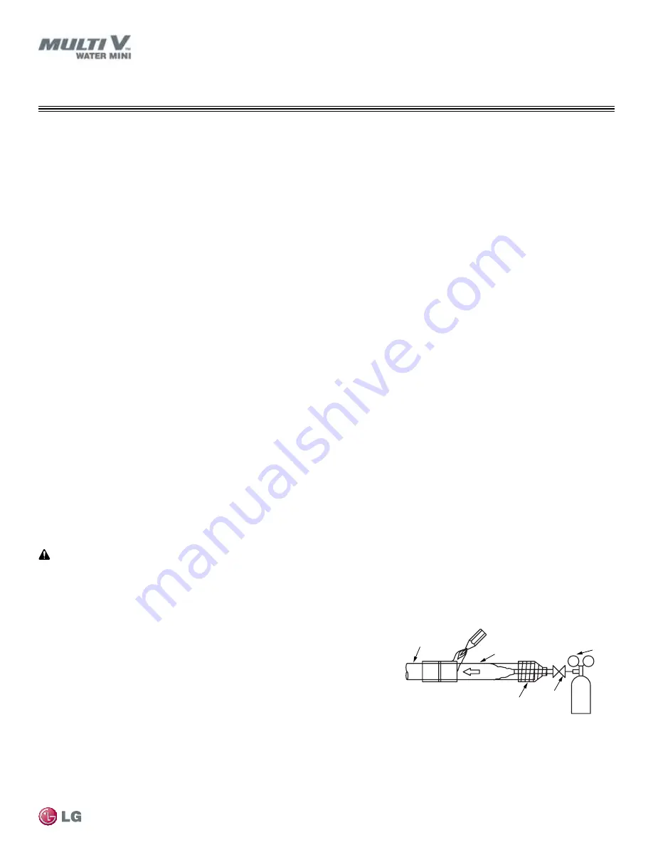
Installation of Refrigerant Piping / Brazing Practices
Figure 21: Refrigerant Pipe Brazing.
Pressure-reducing
Valve
Valve
Taping
Nitrogen
Pipe to
be brazed
Refrigerant
Piping
It is imperative to keep the piping system free of contaminants and debris such as copper burrs, slag, or carbon dust during installation.
Note:
1. All joints are brazed in the field. Multi V Water Mini refrigeration system components contain very small capillary tubes, small orifices,
electronic expansion valves, oil separators, and heat exchangers that can easily become blocked. Proper system operation depends on
the installer using best practices and utmost care while assembling the piping system.
• Store pipe stock in a dry place; keep stored pipe capped and clean.
• Blow clean all pipe sections with dry nitrogen prior to assembly.
2. Proper system operation depends on the installer using best practices and the
utmost care while assembling the piping system.
• Use adapters to assemble different sizes of pipe.
• Always use a non-oxidizing material for brazing. Do not use flux, soft solder, or
anti-oxidant agents. If the proper material is not used, oxidized film may accu-
mulate and clog or damage the compressors. Flux can harm the copper piping or
refrigerant oil.
• Use a tubing cutter, do not use a saw to cut pipe. De-bur and clean all cuts before assembly.
3. Brazing joints:
• Use a dry nitrogen purge operating at a minimum pressure of three (3) psig and maintain a steady flow.
•
Use a 15% silver phosphorous copper brazing alloy to avoid overheating and produce good flow.
• Protect isolation valves, electronic expansion valves, and other heat-sensitive control components from excessive heat with a wet rag or
heat barrier spray.