


Page 72
to +10 VDC control voltage drain for the ballast. There are sufficient terminals for
the purple (+V) control wire for up to eight circuits using these ballasts. Therefore
the maximum number of circuits with this type ballasts that can be fed from one
a-2000D dimmer cabinet is eight. The system automatically assigns outputs in
order of these dimmer types. Refer to the Configuring and Programming Section
to determine that assignment. There is also a group of terminals for the
(common) gray ballast control wires.
Since these are dual dimmers, one half of the dimmer provides the On/Off line
voltage to the ballast, and for that same position the 0 VDC to +10 VDC signal is
available to tell the ballast what brightness is required.
Two-Wire Fluorescent Ballasts
(Additional Control Wiring is not required)
A second method of control, used by the Advance Mark X
TM
fluorescent dimmer
ballast and certain Lutron dimmer ballasts called TU Wire™, uses the power feed
wires to the dimmer for both power and control. Only half of a dual dimmer is
required to drive the ballast since it serves to dim both the ballast and as an On/
Off switch to turn the lights fully off when necessary. In this configuration, the
dimmer output that controls the light intensity is not allowed to go below some
value of true RMS voltage in order to allow the ballast to generate the correct
amount of filament voltage for the fluorescent lamps. By selecting the correct
ballast type in setup, the digital circuitry of the a-2000D control board
automatically sets the correct minimum voltage for the ballast type selected.
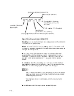
Other Ballasts - Three-Wire- (
Refer to the load wiring schematic.)
A third method of control used by Lutron Hi Lume™ or Eco 10™ ballasts and older
core and coil type magnetic dimming ballasts uses Universal Dimmer Module
(000-A20UN-012, -027). There are three power wires to the ballast, which differs
from other dimming ballasts on the market.
The first power wire supplies line voltage whose output is varied by the dimmer &
is connected to the lower dimmer load terminal.
The second power wire supplies line voltage that must be switched on and off is
connected to the corresponding upper switching load terminal.
The third power wire is the neutral return.
This dimmer module uses only one input breaker to feed the dimming load & the
switching load.
A minimum light level must be set for the Lutron ballasts, depending on
the particular ballast being used. Operating the ballasts below that
minimum level can result in damage to the ballast and lamps.
Содержание a-2000
Страница 2: ...Notes ...
Страница 6: ...Page 4 ...
Страница 78: ...Page 76 ...
Страница 82: ...Page 80 ...


