


a-2000 User Guide
a-2000
Page 71
Dimmer Cabinets with Digital Controls
Revision G November 2006
Dual Universal Module 000-A20UN-012(120V), -027 (120/
277V)
The 000-A20UN-012 & -027 dimmer
is capable of driving on its dimming channels
(lower load terminals):
•
Regular incandescent, quartz, quartz halogen, tungsten argon and similar lamp
loads
•
Magnetic stepdown transformers to operate low voltage incandescent lamp
types
•
Certain electronic stepdown transformers (Check exact types for compatibility)
•
Neon and cold cathode transformers, of the low power factor type
•
Fluorescent dimmer ballasts requiring 0 VDC to +10 V DC control signals (up to
8)
•
Fluorescent dimmer ballasts using two wires for both power and control using
the Advance Mark X dimming ballasts
•
Fluorescent dimmer ballasts using two wires for both power and control using
the Lutron TuWire™ ballasts
•
Non-dim loads that need to be only turned on and off by the module, not
dimmed
•
Dimmed loads that require complete turn off at some point (done by correctly
programming each dimmer slot for the load that is to be connected)
There are many different types and brands of fluorescent dimming ballasts and
electronic low voltage transformers; many of these require different types of
dimmers, modules, and control configurations. If the dimmer ballasts found on a
job site are different than the system was designed to drive, it is necessary to
check with the factory for ballast compatibility. We can assist you in verifying
whether the existing dimmer will drive this different ballast, or whether we
suggest changes to accommodate the different ballast type.
The Lutron company makes a series of dimmer ballasts called HiLume™ and Eco-
10™ that control differently than other dimmer ballasts on the market. The 000-
A20HL-027 dimmer module can drive these ballasts. It has two output terminals.
One provides the 120V (-027, 277V)line voltage and is switched On or Off. The
other output terminal provides a symmetrical phase-controlled dimmer output
with a low end limit as required to drive these ballasts to different light outputs.
The dimmed circuit is connected to the lower load terminal. The switched circuit is
connected to associated upper load terminal. The upper terminals are for ballast
loads only.
Fluorescent Dimming Ballast Types
0-10 VDC Controlled Ballasts
This method of ballast control is used by Sylvania, MagneTek, Advance (for the
Mark VII ballasts) and others. It requires that the line voltage feed to the ballasts
be switched On for operation, and Off to achieve zero light level, because these
ballasts do not dim all the way to blackout.
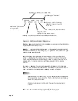
One half of a dual dimmer module is used as an On/Off switch as described
above, and feeds the line voltage to the dimmer ballast. A row of screw
compression terminals located along the top of the PC board provides the 0 VDC
Содержание a-2000
Страница 2: ...Notes ...
Страница 6: ...Page 4 ...
Страница 78: ...Page 76 ...
Страница 82: ...Page 80 ...


