


Commissioning
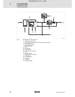
Course program
Commissioning steps
5
74
SW-HB 13.0002-EN EN 3.0
5.5.2
Commissioning steps
Commissioning steps
Comments
1.
Use a serial cable to connect the serial controller interface X1 with a free
COM port on your notebook/PC.
2.
Switch on the control voltage, do
not yet switch on the power supply
!
When the green LED (state) is on, the
voltage is within the permissible range.
3.
Start the »Small Drive Control (SDC)« parameterisation software.
If the ”Online” button in the toolbar is
highlighted in green, the communication
parameters have been set correctly.
4.
Open the menu
Parameters
Device parameters
Motor data
Select
new motor
and select a motor from the Lenze motor database.
Apart from the motor data, this menu
also includes default settings for the
feedback system and the current and
speed controller.
75
5.
Select ”Positioning Course program (DIN3)” from the Commands window.
76
6.
Open the menu
Parameters
I/Os
Digital inputs
and activate ”AIN’s
used as DIN’s”.
77
7.
Open the menu
Parameters
Positioning
Settings position sets / course
program
to select the positioning range and activate ”Course program
active” in the Course program field.
79
8.
Open the menu
Parameters
Positioning
Destination parameters
and
parameterise the position sets.
80
9.
Open the menu
Parameters
Positioning
Course program
and create
the course program.
84
10.
Ensure that the controller is inhibited!
If the controller is only enabled via the
digital input DIN9, set the input to LOW.
DIN9 = LOW
94
11.
Switch on the power supply.
12.
Check, if any error messages have occurred.
First, remove and acknowledge the errors
or change the error management.
13.
Ensure that the drive can rotate without load!
14.
Open the menu
Parameters
Device parameters
Motor data
and click
Auto detect
.
This selection calibrates the motor and
the feedback system.
75
15.
Click the ”Save parameters” icon in the menu bar to save the settings
fail-safe in the EEPROM of the controller.
16.
Enable the controller.
If the controller is only enabled via the
digital input DIN9, set the input to HIGH.
The yellow LED (power) goes on.
DIN9 = HIGH.
94
17.
Start the course program.
The defined positions will be approached
depending on the assignment of the
digital inputs DIN4 and DIN5.
efesotomasyon.com - Lenze