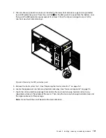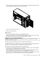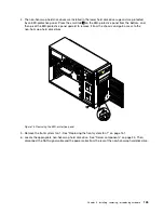
Installing or replacing an optical drive
Attention:
Do not open your server or attempt any repair before reading and understanding “Safety information”
on page iii and “Guidelines” on page 75.
This topic provides instructions on how to install or replace an optical drive.
The EMI integrity and cooling of the server are protected by having all drive bays covered or occupied. Your
server has two optical drive bays. If only one optical drive is installed in the lower bay, the upper bay is
covered by a metal EMI shield on the chassis and also a plastic shield on the front bezel. When you install a
secondary optical drive, save the removed EMI shield from the chassis and plastic shield from the front bezel
in the event that you later remove the drive and need the shields to cover the drive bay.
Attention:
An unoccupied drive bay without any other protection might impact the EMI integrity and cooling
of the server, which might result in overheating or component damage. To maintain the EMI integrity and
cooling of the server, install a new optical drive as soon as you remove the failing one or the protective shields.
CAUTION:
When laser products (such as CD-ROMs, DVD drives, fiber optic devices, or transmitters) are
installed, note the following:
• Do not remove the covers. Removing the covers of the laser product could result in exposure to
hazardous laser radiation. There are no serviceable parts inside the device.
• Use of controls or adjustments or performance of procedures other than those specified herein
might result in hazardous radiation exposure.
DANGER
Some laser products contain an embedded Class 3A or Class 3B laser diode. Note the following:
Laser radiation when open. Do not stare into the beam, do not view directly with optical
instruments, and avoid direct exposure to the beam.
Before you begin, review the following optical drive installation rules:
• The server has two optical drive bays. If your server has only one optical drive installed, ensure that the
optical drive is installed in the lower bay (optical drive bay 1). The upper bay is for a secondary optical
drive.
• The following table provides information about the recommended power connector and connector on the
system board for the installed optical drive. See “Server components” on page 25 for the locations of
the optical drive bays and “System board components” on page 42 for the locations of the connectors
on the system board.
Drive bay
Drive
Power connector
Connector on the system board
Optical drive bay 1 (lower
bay)
An optical drive installed
P11
SATA 5 connector
Optical drive bay 2 (upper
bay)
An optical drive installed in
some models
P12
SATA 4 connector
Before you begin, print all the related instructions or ensure that you can view the PDF version on another
computer for reference.
120
ThinkServer TD330 Hardware Maintenance Manual
Содержание ThinkServer TD330
Страница 14: ...xii ThinkServer TD330 Hardware Maintenance Manual ...
Страница 18: ...4 ThinkServer TD330 Hardware Maintenance Manual ...
Страница 20: ...6 ThinkServer TD330 Hardware Maintenance Manual ...
Страница 64: ...50 ThinkServer TD330 Hardware Maintenance Manual ...
Страница 88: ...74 ThinkServer TD330 Hardware Maintenance Manual ...
Страница 204: ...190 ThinkServer TD330 Hardware Maintenance Manual ...
Страница 216: ...202 ThinkServer TD330 Hardware Maintenance Manual ...
Страница 217: ......
Страница 218: ......


