


(cy1cd020)
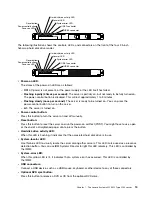
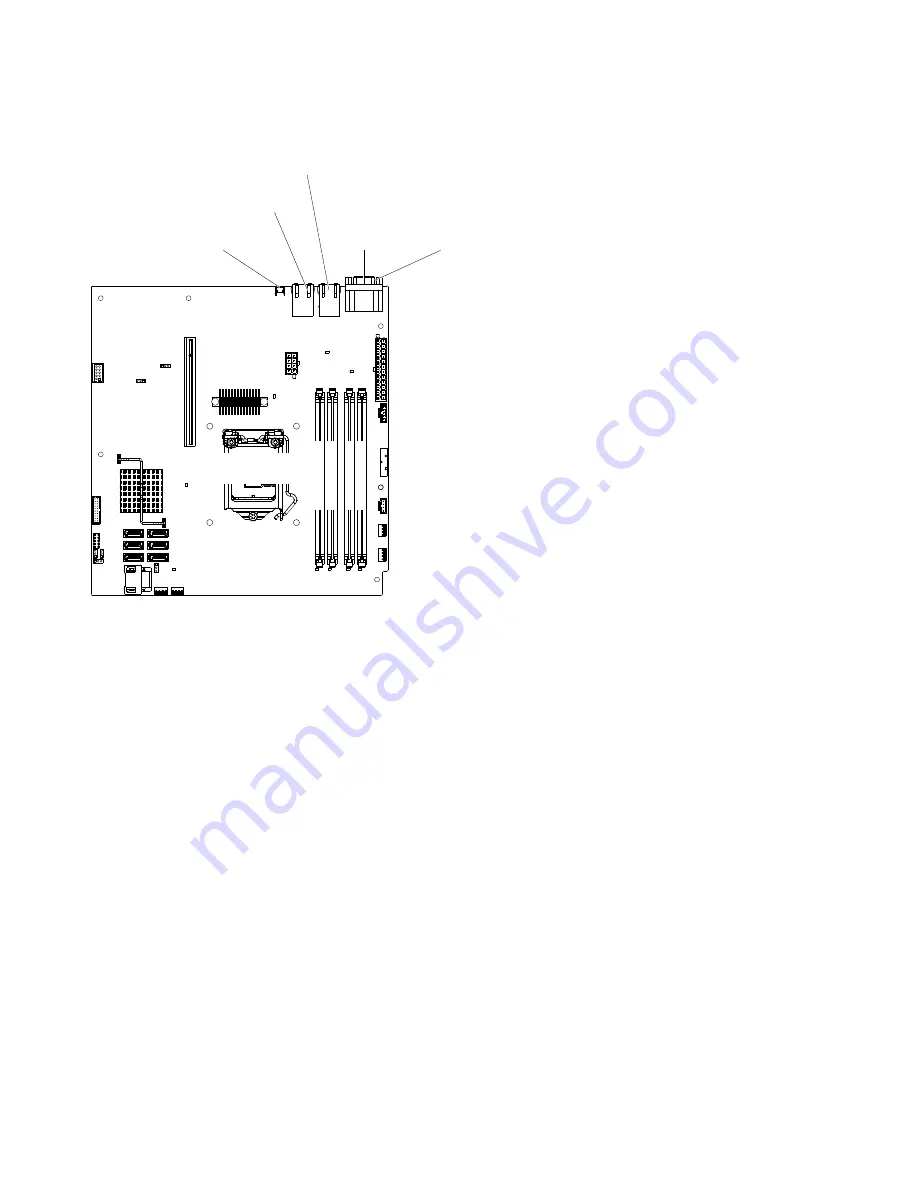
DIMM 1
DIMM 2
DIMM 3
DIMM 4
Microprocessor
Video
Serial (COM1)
NMI button
Ethernet connector 2/
USB connectors 3&4
Ethernet connector 1/
USB connectors 1&2
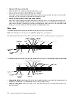
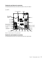
Figure 4. External connectors on the system board
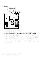
System-board switches and jumpers
The following illustration shows the location and description of the switches, jumpers, and buttons.
Important:
1. Before you change any switch settings or move any jumpers, turn off the server; then, disconnect all
power cords and external cables. Review the information in “Safety” on page v, “Installation guidelines”
on page 33, and “Turning off the server” on page 15.
2. Any system-board switch or jumper block that is not shown in the illustrations in this document are
reserved.
3. If there is a clear protective sticker on the top of the switch blocks, you must remove and discard it to
access the switches.
22
Lenovo System x3250 M4 Installation and Service Guide
Содержание System x3250 M4
Страница 1: ...Lenovo System x3250 M4 Installation and Service Guide Machine Type 2583 ...
Страница 6: ...iv Lenovo System x3250 M4 Installation and Service Guide ...
Страница 74: ...60 Lenovo System x3250 M4 Installation and Service Guide ...
Страница 98: ...84 Lenovo System x3250 M4 Installation and Service Guide ...
Страница 136: ...122 Lenovo System x3250 M4 Installation and Service Guide ...
Страница 144: ...130 Lenovo System x3250 M4 Installation and Service Guide ...
Страница 418: ...404 Lenovo System x3250 M4 Installation and Service Guide ...
Страница 596: ...582 Lenovo System x3250 M4 Installation and Service Guide ...
Страница 604: ...Taiwan BSMI RoHS declaration 590 Lenovo System x3250 M4 Installation and Service Guide ...
Страница 612: ...598 Lenovo System x3250 M4 Installation and Service Guide ...
Страница 613: ......
Страница 614: ......


