

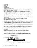
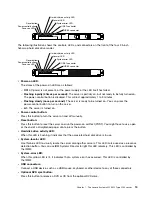


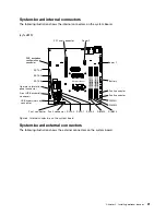
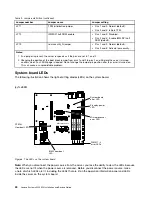


System-board internal connectors
The following illustration shows the internal connectors on the system board.
(cy1cd019)
DIMM 1
DIMM 2
DIMM 3
DIMM 4
Microprocessor
Power 2
Battery
Fan 4 connector
Fan 3 connector
DIMM 1
DIMM 2
DIMM 3
DIMM 4
Fan 2 connector
Fan 1 connector
SATA 2
SATA 1
SATA 0
SATA 3
SATA 4
SATA 5
Operator information
panel connector
Front USB assembly
connecotr
USB hypervisor key
connector
PCI riser connector
Power 1
SAS backplane
configuration
connector
Figure 3. Internal connectors on the system board
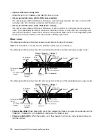
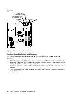
System-board external connectors
The following illustration shows the external connectors on the system board.
21
Содержание System x3250 M4
Страница 1: ...Lenovo System x3250 M4 Installation and Service Guide Machine Type 2583 ...
Страница 6: ...iv Lenovo System x3250 M4 Installation and Service Guide ...
Страница 74: ...60 Lenovo System x3250 M4 Installation and Service Guide ...
Страница 98: ...84 Lenovo System x3250 M4 Installation and Service Guide ...
Страница 136: ...122 Lenovo System x3250 M4 Installation and Service Guide ...
Страница 144: ...130 Lenovo System x3250 M4 Installation and Service Guide ...
Страница 418: ...404 Lenovo System x3250 M4 Installation and Service Guide ...
Страница 596: ...582 Lenovo System x3250 M4 Installation and Service Guide ...
Страница 604: ...Taiwan BSMI RoHS declaration 590 Lenovo System x3250 M4 Installation and Service Guide ...
Страница 612: ...598 Lenovo System x3250 M4 Installation and Service Guide ...
Страница 613: ......
Страница 614: ......


