IOM / ROOF-TOP FLEXY™ Series - Page 41
FX AIR FLOW BALANCING
1.
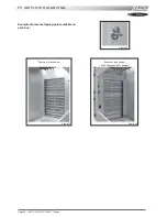
Operation of the grids
- Balancing grids are installed on fresh air side in order to compensate for the higher pressure drop on the ducted return
air side.
- The aim is to avoid the pressure variations in the area to air conditioned (risk of doors opening in cinemas for example)
but also to avoid a current surge on the motor when running 100% fresh air.
- The objective is to maintain constant airflow/pressure operating conditions with the supply air, regardless of the
percentage of fresh air.
- Once adjusted the air treatment fans should not see the difference between the ducted return air and the fresh air.
2.
Airside adjustment procedure for the FX with 4 dampers
- Adjust the machine with the 0% fresh air configuration, the grids are open to the maximum.
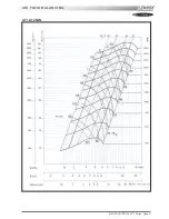
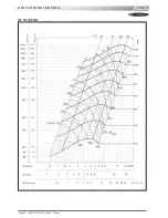
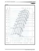
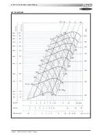
- Measure the Amps and Speed of the "treatment" fan motor. Determine the airflow and pressure using the Fan Curves.
- If the absorbed Amps are higher than the value on the motor plate, the supply and return ducts pressure drop is lower
than the requested value at the time of order. Reduce the rpm, change the Pulleys if necessary.
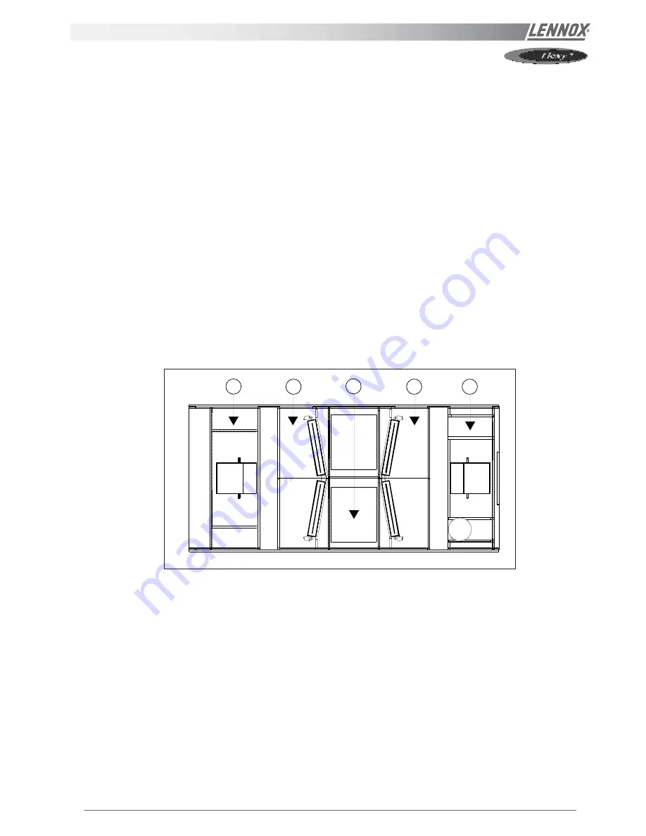
- Once the airflow and pressure have been checked and confirmed, measure the static pressure at the 5 following points :
1a
: "Treatment " fan inlet (ex : -230 Pa)
2a
: "Treatment" expansion box (ex : -210 Pa)
3a
: Return air box (ex : -190 Pa)
4a
: Extraction expansion box (ex : -70 Pa)
5a
: Extraction fan inlet (ex : -120 Pa)
- Adjust the extraction grid to reach a pressure in 4 equal to the pressure in 2 (ex : reach -210 Pa when closing).
- Check the Amps absorbed by the extraction fan motor; It must be lower than the value on the plate otherwise reduce the
fan speed.
- Reverse the fresh air percentage: 100 % fresh air at the treatment.
- Measure the Static pressure at the same 5 points
1b
: "Treatment " Fan Inlet (ex : -80 Pa)
2b
: "Treatment" expansion box (ex : -50 Pa)
3b
: Return air box (ex : -200 Pa)
4b
: Extraction expansion box (ex : -220 Pa)
5b
: Extraction fan inlet (ex : -250 Pa)
- Adjust the grid on the "treatment" side only to reach a pressure at point 2b identical to the pressure at 2a (reach -210 Pa
when closing)
- Check that the pressure measured in the extraction expansion box 5b has not changed too much compared with the
previous measurement 5a. Adjust the bypass grid to compensate any possible difference.
1
2
4
3
5
Figure 25
Содержание ROOFTOP FLEXY FCA 100
Страница 1: ...INSTALLATION OPERATING MAINTENANCE MANUAL ROOFTOP FLEXY English August 2003 ...
Страница 2: ......
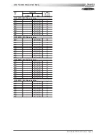
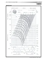
Страница 33: ...IOM ROOF TOP FLEXY Series Page 31 AIR FLOW BALANCING AT 12 12 FAN ...
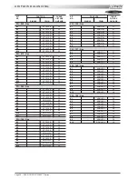
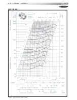
Страница 34: ...Page 32 IOM ROOF TOP FLEXY Series AIR FLOW BALANCING AT 15 15 FAN ...
Страница 35: ...IOM ROOF TOP FLEXY Series Page 33 AIR FLOW BALANCING AT 18 13 ...
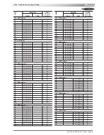
Страница 36: ...Page 34 IOM ROOF TOP FLEXY Series AIR FLOW BALANCING AT 18 18 FAN ...
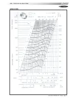
Страница 37: ...IOM ROOF TOP FLEXY Series Page 35 AIR FLOW BALANCING RDN 450 FAN ...
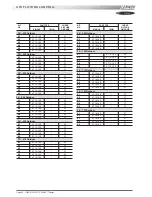
Страница 38: ...Page 36 IOM ROOF TOP FLEXY Series AIR FLOW BALANCING ADN 355 FAN ...
Страница 39: ...IOM ROOF TOP FLEXY Series Page 37 AIR FLOW BALANCING ADN 400 FAN ...
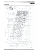
Страница 40: ...Page 38 IOM ROOF TOP FLEXY Series AIR FLOW BALANCING ADN 450 FAN ...
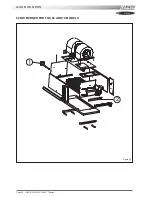
Страница 56: ...Page 54 IOM ROOF TOP FLEXY Series GAS BURNERS 60 KW BURNER FOR FGX 60 AND 70 MODELS 1 2 Figure 63 ...
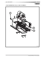
Страница 57: ...IOM ROOF TOP FLEXY Series Page 55 GAS BURNER 120 KW BURNER FOR FGX 60 70 AND 100 MODELS 1 2 3 Figure 64 ...
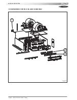
Страница 58: ...Page 56 IOM ROOF TOP FLEXY Series 180 KW BURNER FOR FGX 120 AND 140 MODELS GAS BURNER 1 2 3 Figure 65 ...
Страница 104: ...Page 102 IOM ROOF TOP FLEXY Series ELECTRICAL WIRING DIAGRAMS MAIN CURRENT DIAGRAM ...
Страница 106: ...Page 104 IOM ROOF TOP FLEXY Series ELECTRICAL WIRING DIAGRAMS CLIMATIC CONTROLLER ...
Страница 107: ...IOM ROOF TOP FLEXY Series Page 105 ELECTRICAL WIRING DIAGRAMS CLIMATIC INPUT FC FH FX Confort Set Point GTC ...
Страница 108: ...Page 106 IOM ROOF TOP FLEXY Series ELECTRICAL WIRING DIAGRAMS CLIMATIC INPUT FG FD ...
Страница 111: ...IOM ROOF TOP FLEXY Series Page 109 ELECTRICAL WIRING DIAGRAMS WIRING DIAGRAM GAS BURNER 33 60 120 Kw ...
Страница 112: ...Page 110 IOM ROOF TOP FLEXY Series ELECTRICAL WIRING DIAGRAMS GAS BURNER 180 Kw ...
Страница 132: ...Page 130 IOM ROOF TOP FLEXY Series ISO 9001 CERTIFICATION ...
Страница 133: ...IOM ROOF TOP FLEXY Series Page 131 PED CERTIFICATION OF CONFORMITY ...
Страница 134: ...Page 132 IOM ROOF TOP FLEXY Series GLASS WOOL FIRE CLASS ...
Страница 135: ...IOM ROOF TOP FLEXY Series Page 133 33 kW GAS BURNER CE CERTIFICATION OF CONFORMITY ...
Страница 136: ...Page 134 IOM ROOF TOP FLEXY Series 60 kW GAS BURNER CE CERTIFICATION OF CONFORMITY ...
Страница 137: ...IOM ROOF TOP FLEXY Series Page 135 120 kW GAS BURNER CE CERTIFICATION OF CONFORMITY ...
Страница 138: ...Page 136 IOM ROOF TOP FLEXY Series 180 kW GAS BURNER CE CERTIFICATION OF CONFORMITY ...
Страница 139: ...IOM ROOF TOP FLEXY Series Page 137 INSULATION FIRE CLASS ...
Страница 140: ...Page 138 IOM ROOF TOP FLEXY Series INSULATION FIRE CLASS ...
Страница 141: ......

