background image

IOM / ROOF-TOP FLEXY™ Series - Page 27

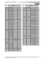
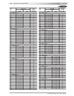
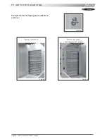
AIRFLOW BALANCING

KIT

FAN TYPE

CURVE

NR

PICTURE

SINGLE

TWIN

ON PAGE

FC/FH/FD... 085 - Side discharge

K14

-

AT 15-15 S

32

K15

-

AT 15-15 S

32

K16

-

AT 15-15 S

32

K17

-

AT 15-15 S

32

K18

-

AT 15-15 S

32

K19

-

AT 15-15 S

32

K20

-

AT 15-15 S

32

K21

-

AT 15-15 S

32

FC/FH/FD... 100 - Side discharge

K10

-

AT 15-15 S

32

K11

-

AT 15-15 S

32

K12

-

AT 15-15 S

32

K13

-

AT 15-15 S

32

K14

-

AT 15-15 S

32

K15

-

AT 15-15 S

32

K16

-

AT 15-15 S

32

K17

-

AT 15-15 S

32

K18

-

AT 15-15 S

32

K19

-

AT 15-15 S

32

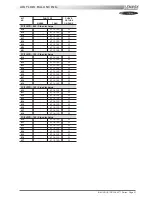
FC/FH/FD... 120 - Side discharge

K10

-

AT 18-13 S

33

K11

-

AT 18-13 S

33

K12

-

AT 18-13 S

33

K13

-

AT 18-13 S

33

K14

-

AT 18-13 S

33

K15

-

AT 18-13 S

33

K16

-

AT 18-13 S

33

K17

-

AT 18-13 S

33

K18

-

AT 18-13 S

33

FC/FH/FD... 140 - Side discharge

K10

-

AT 18-13 S

33

K11

-

AT 18-13 S

33

K12

-

AT 18-13 S

33

K13

-

AT 18-13 S

33

K14

-

AT 18-13 S

33

K15

-

AT 18-13 S

33

K16

-

AT 18-13 S

33

K17

-

AT 18-13 S

33

Содержание ROOFTOP FLEXY FCA 100

Страница 1: ...INSTALLATION OPERATING MAINTENANCE MANUAL ROOFTOP FLEXY English August 2003 ...

Страница 2: ......

Страница 3: ...K 35 FXK 40 FXK 55 FXK 70 FXK 85 FXK 100 FXK 110 FXK 140 FXK 170 The technical information and specifications contained in this manual are for reference only The manufacturer reserves the right to modify these without warning and without obligation to modify equipment already sold Ref FLEXY_IOM 0803 E NOTES FOR UNIT FITTED WITH GAS BURNER THE UNIT MUST BE INSTALLED IN ACCORDANCE WITH LOCAL SAFETY ...

Страница 4: ...GRAPHICAL DISPLAY 72 BMS CONTACTS KIT 81 CLIMATIC PARAMETERS 82 CONTROL INTERFACE CLIMALINK CLIMALOOK 88 WIRING DIAGRAMS ELECTRICAL WIRING DIAGRAMS LIST OF ITEMS 96 ELECTRICAL WIRING DIAGRAMS 100 TROUBLESHOOTING SAFETYAND ERROR CODES 117 MAINTENANCE DIAGNOSTIC 123 MAINTENANCE PLAN 126 WARRANTY 129 CERTIFICATES ISO 9001 CERTIFICATION 130 PED CERTIFICATION OF CONFORMITY 131 GLAS WOOL FIRE CLASS 132 ...

Страница 5: ... purpose and suitable equipment To prevent the risk of explosion due to spraying of coolant and oil the relevant circuit shall be drained and at zero pressure before any disassembly or unbrazing of the refrigerating parts takes place There is a residual risk of pressure build up by degassing the oil or by heating the exchangers after the circuit has been drained Zero pressure shall be maintained b...

Страница 6: ... the maximum value likely to be achieved for the specified operational voltage The customer must have a suitable electrical supply It is therefore important to check whether the supply voltage stated on the unit s rating plate is compatible with that of the mains electrical supply The rating plate also states the year of manufacture as well as the type of refrigerant used and the required charge f...

Страница 7: ... X 2875 2285 2070 630 1270 2590 1855 FC FH 070 GAS X X X 2825 2255 1470 630 1230 1300 2210 X X X 2875 2255 2070 630 1400 1470 2590 1855 FC FH 085 Cooling only and heat pump X X X 3785 2255 1495 630 1220 2830 2330 X X X 3785 2255 1495 630 1270 2830 2330 X X X X X 3785 2285 1495 630 1275 2830 2330 X X X 3835 2255 2080 630 1435 3230 2430 1870 X X X 3835 2255 2080 630 1485 3230 2430 1870 X X X X X 383...

Страница 8: ...1880 X X X X X 3635 2285 1930 630 1975 3000 2410 1880 FG 140 GAS X X X 4035 2255 1470 630 1920 1970 3000 2310 X X X 4085 2255 1930 630 2000 2050 3300 2700 2080 FC FH 160 Cooling only and heat pump X X X 3595 2255 2070 900 2050 2700 2090 X X X 3595 2255 2070 900 2120 2700 2090 X X X X X 3595 2285 2070 900 2140 2700 2090 X X X 3645 2255 2070 900 2275 2700 2090 X X X 3645 2255 2070 900 2345 2700 2090...

Страница 9: ...ize to avoid damaging the equipment Sling length 2210 mm for angle 45 C FC FH FD FG 060 070 LENGTH HEIGHT WIDTH AUVENT WEIGHT kg lateral ventil standard MODELS mm mm mm mm mm kg FX 025 4070 1635 1055 490 600 950 FX 030 4070 1635 1055 490 600 980 FX 035 4750 2255 1290 490 600 1400 FX 040 4750 2255 1290 490 600 1450 FX 055 4750 2255 1290 490 600 1600 FX 070 5050 2255 1725 890 600 1800 FX 085 5050 22...

Страница 10: ...0 mm for angle 45 C Sling length 2330 mm for angle 64 5 C FC FH FD FG 085 100 Sling length 2430 mm for angle 45 C FC FH FD FG 085 100 with centrifugal fans Sling length 3230 mm for angle 45 C Sling length 2830 mm for angle 45 C Sling length 1870 mm for angle 45 C Figure 3 for all handling drawings pages 7 to11 ...

Страница 11: ...h 2700 mm for angle 45 C Sling length 2410 mm for angle 45 C FC FH FD 120 140 with centrifugal fans Sling length 2080 mm for angle 45 C FG 120 140 with gas burner Sling length 2700 mm for angle 45 C Sling length 3000 mm for angle 45 C Sling length 1880 mm for angle 45 C Figure 3 for all handling drawings pages 7 to11 ...

Страница 12: ... 3300 mm for angle 45 C Sling length 2080 mm for angle 45 C Sling length 2090 mm for angle 45 C FC FH FD 160 190 FC FH FD 160 190 with centrifugal fans Sling length 2700 mm for angle 45 C Sling length 2320 mm for angle 45 C FG 160 190 FG 160 190 with centrifugal fans Sling length 3000 mm for angle 45 C Figure 3 for all handling drawings pages 7 to11 ...

Страница 13: ...LING FX 25 30 Sling length 1 3000 mm Sling length 2 2350 mm 1 1 2 FX 35 40 55 Sling length 1 3700 mm Sling length 2 2850 mm 1 1 2 Sling length 1 3900 mm Sling length 2 3000 mm FX 70 85 100 1 1 2 Sling length 1 4300 mm Sling length 2 3250 mm FX 110 140 170 ...

Страница 14: ...obstructing the duct connections or hindering assembly and maintenance access INSTALLATION Figure 5 INSTALLATION REQUIREMENTS The surface on which the equipment is to be installed must be clean and free of any obstacles which could hinder the flow of air to the condensers Avoid uneven surfaces Avoid installing two units side by side or close to each other as this may restrict the airflow to the co...

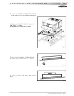
Страница 15: ...lation of the equipment Above all ensure that all the adjustable returns are facing outward 1 figure 6 They are usually turned inside out for transport Place the roof mounting frame on the trimmer beam by first lining up the inlet and then the outlet 2 figure 7 After levelling the frame fix the surface flaps onto the trimmer 1 Figure 6 Figure 7 Figure 8 ...

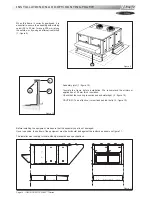
Страница 16: ...re installation We recommend the minimum application of 25 mm thick insulation Check that the covering is continuous and watertight 2 figure 10 CAUTION To be effective it must finsh behind the lip 3 figure 10 Before installing the equipment make sure that the assembly seal is not damaged Once in position the bottom of the equipment must be horizontal and against the roofcurb as shown on figure 11 ...

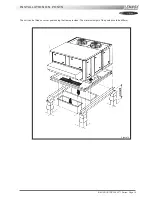
Страница 17: ...IOM ROOF TOP FLEXY Series Page 15 INSTALLATION ON POSTS The unit can be fitted on corner posts using the frame provided The minimum height of the posts should be 400mm Figure 12 ...

Страница 18: ...MATIC controller Once the fan is running check the rotation direction Refer to the rotation arrow on the fan The fan and other components direction of rotation is checked during an end of line test They should therefore all turn in the same direction If they run in the opposite direction disconnect the power supply to the machine at the building s mains switch reverse two phases of the incoming su...

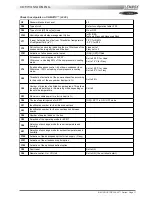
Страница 19: ...ading of compressors in cooling mode Set to 12 0 C for Linea Set to 5 0 C for Flexy C49 Threshold of activation of the power exhaust fan according to the position of the economiser damper in Set to 50 C46 Number of minutes of anticipation per degrees This allows an anticipated start up in the morning mode depending on the outside temperature Set to 0 C83 Maximum usable power for electric heat in C...

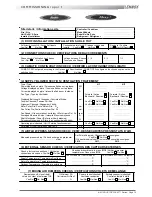
Страница 20: ... current drawn against the rated values in particular on the supply fan If the readings on the fan are outside the specified limits this usually indicates excessive air flow which will affect the life expectancy and the thermodynamic performan ces of the unit This will also increase the risks of water ingress into the unit Refer to the air flow balancing section to correct the problem At this poin...

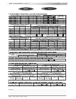
Страница 21: ...11 3412 6 EXTERNAL SENSOR CHECKS VERIFICATION DES CAPTEURS EXTERNES Check and record temp in menu 2110 Vérifier et mesurer les températures Dans menu 2110 Yes Oui No Non Check electrical connections Vérification des connections électriques Yes Oui No Non 100 Fresh Air 100 Air neuf 100 return Air 100 Air repris Supply Temperature Température Soufflage C C Return Temperature Température reprise C C ...

Страница 22: ... A A C C Bar Bar HP cut out Coupure HP Bar LP cut out Coupure sécurité BP Bar Refrigerant charge Charge réfrigérant C1 kg C2 kg C3 kg C4 kg 9 ELECTRIC HEATER SECTION SECTION RECHAUFFEUR ELECTRIQUE Type Type Serial No No Série AMPS 1 st stage Baltic Intensité 1 er étage Baltic AMPS 2 nd stage Baltic Intensité 2 e étage Baltic 1 2 3 1 2 3 10 HOT WATER COIL SECTION SECTION BATTERIE EAU CHAUDE Check T...

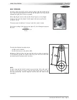
Страница 23: ...centre to centre Check that according to the diagram below figure 18 the following ratio remains the same A m 20 P mm The belts should always be replaced when the disk is set to maximum the belt rubber is worn or the wire is visible Replacement belts must have the same rated size as the ones they are replacing If a transmission system has several belts they must all be from the same manufacturing ...

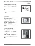
Страница 24: ...h hands and shake it vigorously to make sure everything is in place Fill the holes with grease for protection NOTE During installation the key should never protrude out of its groove After 50 operating hours check that the screws are still in place Motor pulley installation and removal The pulley is held in position by the key and a screw located in the groove After unlocking removing this screw b...

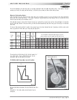
Страница 25: ...ary lock the main switch First unscrew the 4 Allen screw s on the pulley see figure 23 0 5 1 1 5 2 2 5 3 3 5 4 4 5 5 0 5 5 8450 120 95 116 5 113 9 111 8 109 7 107 6 105 5 103 4 101 3 99 2 97 1 95 0 D8450 20 2 28 0 5 21 0 21 8 22 5 23 3 24 1 24 9 25 7 26 4 27 2 28 0 8550 136 110 131 5 128 9 126 8 124 7 122 6 120 5 118 4 116 3 114 2 112 1 110 0 D8550 20 6 31 2 5 21 6 22 7 23 8 24 8 25 9 26 9 28 0 29...

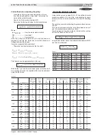
Страница 26: ...re drop table Also the pressure drop due to the duct inlet into the roof top unit can be taken as 20 to 30 Pa P INT P filter coil P Inlet P Options using the results from above the external static pressure ESP can then be estimated ESP PTOT Pd PINT Table 2 Motor Size Nom Speed Cos meca motor 0 75 kW 1400 rpm 0 77 0 70 1 1 kW 1425 rpm 0 82 0 77 1 5 kW 1430 rpm 0 81 0 75 2 2 kW 1430 rpm 0 81 0 76 3 ...

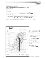
Страница 27: ...urn from fully closed or measured distance between pulley end plates is 21 8 mm from table xxx it can be determined that the motor pulley has a diameter of 111 8 mm rpm FAN rpm MOTOR x DM DF 1430 x 118 2 250 640 rpm Using the fan curve below the operating point can be located It can be determined that the fan is providing approximately 12 000 m3 h with a total pressure PTOT 420 Pa 640 420 12 10 1 ...

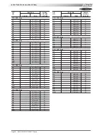
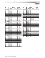
Страница 28: ...K13 AT 15 15 S 32 FC FH FD 100 Standard K1 AT 15 15 G2L 32 K2 AT 15 15 G2L 32 K3 AT 15 15 G2L 32 K4 AT 15 15 G2L 32 K5 AT 15 15 G2L 32 K6 AT 15 15 S 32 K7 AT 15 15 G2L 32 K8 AT 15 15 S 32 K9 AT 15 15 G2L 32 KIT FAN TYPE CURVE NR PICTURE SINGLE TWIN ON PAGE FC FH FD 120 Standard K1 AT 18 18 S 34 K2 AT 18 18 S 34 K3 AT 18 18 S 34 K4 AT 18 18 S 34 K5 AT 18 18 S 34 K6 AT 18 18 S 34 K7 AT 18 18 S 34 K8...

Страница 29: ...11 AT 15 15 S 32 K12 AT 15 15 S 32 K13 AT 15 15 S 32 K14 AT 15 15 S 32 K15 AT 15 15 S 32 K16 AT 15 15 S 32 K17 AT 15 15 S 32 K18 AT 15 15 S 32 K19 AT 15 15 S 32 FC FH FD 120 Side discharge K10 AT 18 13 S 33 K11 AT 18 13 S 33 K12 AT 18 13 S 33 K13 AT 18 13 S 33 K14 AT 18 13 S 33 K15 AT 18 13 S 33 K16 AT 18 13 S 33 K17 AT 18 13 S 33 K18 AT 18 13 S 33 FC FH FD 140 Side discharge K10 AT 18 13 S 33 K11...

Страница 30: ...15 15 S 32 K10 ADN 325L 36 K11 ADN 325L 36 FG 100 Gas K1 AT 15 15 S 32 K2 AT 15 15 S 32 K3 AT 15 15 S 32 K4 AT 15 15 S 32 K5 ADN 325L 36 K6 AT 15 15 S 32 K7 AT 15 15 S 32 K8 ADN 325L 36 K9 AT 15 15 S 32 K10 ADN 325L 36 KIT FAN TYPE CURVE NR PICTURE SINGLE TWIN ON PAGE FG 120 Gas K1 ADN 370L 37 K2 ADN 370L 37 K3 ADN 370L 37 K4 ADN 370L 37 K5 ADN 370L 37 K6 ADN 370L 37 K7 ADN 370L 37 K8 ADN 370L 37 ...

Страница 31: ...5 15 S 32 K5 AT 15 15 S 32 K6 AT 15 15 S 32 K7 AT 15 15 S 32 K8 AT 15 15 S 32 K9 AT 15 15 S 32 K10 AT 15 15 S 32 KIT FAN TYPE CURVE NR PICTURE SINGLE TWIN ON PAGE FX 070 Indoor K1 AT 18 18 S 34 K2 AT 18 18 S 34 K3 AT 18 18 S 34 K4 AT 18 18 S 34 K5 AT 18 18 S 34 K6 AT 18 18 S 34 K7 AT 18 18 S 34 K8 AT 18 18 S 34 K9 AT 18 18 S 34 K10 AT 18 18 S 34 K11 AT 18 18 S 34 FX 085 Indoor K1 AT 18 18 S 34 K2 ...

Страница 32: ... K4 AT 18 18 S 37 K5 AT 18 18 S 37 KIT FAN TYPE CURVE NR PICTURE SINGLE TWIN ON PAGE FX 025 Outdoor K1 AT 12 12 S 31 K2 AT 12 12 S 31 K3 AT 12 12 S 31 K4 AT 12 12 S 31 K5 AT 12 12 S 31 K6 AT 12 12 S 31 FX 030 Outdoor K1 AT 12 12 S 31 K2 AT 12 12 S 31 K3 AT 12 12 S 31 K4 AT 12 12 S 31 K5 AT 12 12 S 31 FX 035 Outdoor K1 AT 15 15 S 32 K2 AT 15 15 S 32 K3 AT 15 15 S 32 K4 AT 15 15 S 32 K5 AT 15 15 S 3...

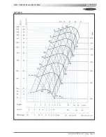
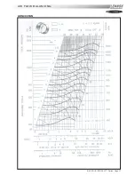
Страница 33: ...IOM ROOF TOP FLEXY Series Page 31 AIR FLOW BALANCING AT 12 12 FAN ...

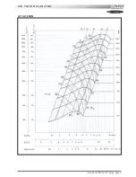
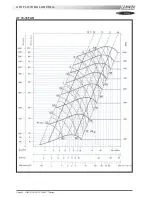
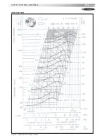
Страница 34: ...Page 32 IOM ROOF TOP FLEXY Series AIR FLOW BALANCING AT 15 15 FAN ...

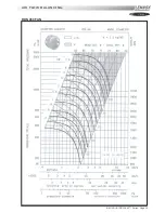
Страница 35: ...IOM ROOF TOP FLEXY Series Page 33 AIR FLOW BALANCING AT 18 13 ...

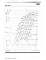
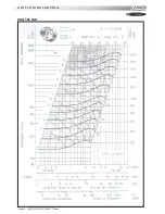
Страница 36: ...Page 34 IOM ROOF TOP FLEXY Series AIR FLOW BALANCING AT 18 18 FAN ...

Страница 37: ...IOM ROOF TOP FLEXY Series Page 35 AIR FLOW BALANCING RDN 450 FAN ...

Страница 38: ...Page 36 IOM ROOF TOP FLEXY Series AIR FLOW BALANCING ADN 355 FAN ...

Страница 39: ...IOM ROOF TOP FLEXY Series Page 37 AIR FLOW BALANCING ADN 400 FAN ...

Страница 40: ...Page 38 IOM ROOF TOP FLEXY Series AIR FLOW BALANCING ADN 450 FAN ...

Страница 41: ... KP17 indicates that the filters are out of position either they have been damaged or not been replaced during maintenance In the latter case the unit has not stopped but the increased flowrate may result in the motor overheating It is important to check the filter immediately FILTER REPLACEMENT After opening the filter access panel unscrew the butterfly nuts maintaining the filter support and rem...

Страница 42: ...ring the last 5 to 30 second The motor reaches nominal speed and the controller is bypassed The motor speed control is achieve through a variation of the supply voltage of each phase at constant frequency The thermal overload limit on the motor imposes a current limitation during the acceleration stage Hence if the selected slope is to steep a predefined current limit can be reached potentiometer ...

Страница 43: ...he requested value at the time of order Reduce the rpm change the Pulleys if necessary Once the airflow and pressure have been checked and confirmed measure the static pressure at the 5 following points 1a Treatment fan inlet ex 230 Pa 2a Treatment expansion box ex 210 Pa 3a Return air box ex 190 Pa 4a Extraction expansion box ex 70 Pa 5a Extraction fan inlet ex 120 Pa Adjust the extraction grid t...

Страница 44: ...2 IOM ROOF TOP FLEXY Series Treatment side damper Extraction side damper fresh air bypass 25 damper FX AIR FLOW BALANCING Figure 27 Figure 28 Example of pressure tapping point available on each box Figure 26 ...

Страница 45: ... m3 h 10 000 m3 h 2 500 m3 h 12 500 m3 h 2 500 m3 h 10 000 m3 h 10 000 m3 h 2 500 m3 h 12 500 m3 h 0 FRESH AIR TREATMENT 100 FRESH AIR TREATMENT CONSTANT 25 BYPASS TO EXTRACTION Fresh air hood Fresh air hood RETURN air duct RETURN air duct SUPPLY air duct EXTRACTION air duct SUPPLY air duct EXTRACTION air duct Treatment fan Treatment fan Extraction fan Extraction fan Grid on damper By pass grid Fi...

Страница 46: ... THE ONLY EFFECTIVE PROTECTION AGAINST FREEZING The antifreeze must protect the unit and avoid icing under winter conditions Warning monoethylene glycol based antifreeze may produce corrosive agents when mixed with air 2 Drain the installation You must ensure that the manual or automatic air vents have been installed on all high points in the system In order to drain the system check that all the ...

Страница 47: ...eering Practice The pipe work connected to each rooftop must not be smaller than the diameter of the connection on the rooftop unit 1 3 Shut off valve in front of each rooftop Make sure that a shut off isolation valve has been installed before EACH rooftop Check that the internal shut off valves in the rooftop unit is open 1 4 Pipe work purging and gas static pressure checks Purge the pipe work ne...

Страница 48: ...he reset button on the gas control block to reset the unit after a fault 3 START UP AND SET UP OF THE GAS UNIT 3 1 General operation check of the system Check that the centrifugal fan blower in the unit is running 3 2 Set up Set the setpoint 59 and 60 to ON This will priorities the gas burner Increase the set temperature 1 room set point temperature to a temperature higher than the room temperatur...

Страница 49: ...ecessary the IN pressure to 20 0 mbar G20 or 37 0 mbar for propane G31 3 5 High heat injection pressure checks Fit the tube of the accurate Manometer to the OUT port on the HONEYWELL valve after having loosened the screw Check and adjust if necessary the OUT pressure to 8 4 mbar G20 or 31 4 mbar for propane G31 3 6 Low heat injection pressure checks Carefully disconnect the wire numbered 116 for t...

Страница 50: ...reconnecting of the tube the burner will restart after 30 seconds of pre ventilation 4 2 Gas pressure switch test With the gas burner running close the internal shut off valve in the rooftop The burner stops completely However No fault light will be displayed on the Honeywell Control box After 6 Minutes the CLIMATIC 2 will display fault 14 or 15 Reset the CLIMATIC 2 4 3 Ionisation probe test With ...

Страница 51: ... the gas rail Disconnect the electrical connector on the electric board EF45 or 46 Remove the two screws which hold the gas bar in place Carefully remove the gas rail avoiding any damaged to the electrodes 5 4 Disassembling the chimneys Electrically disconnect the fan and remove the screws holding it in place Take care not to loose any cage nuts in the smoke bos Attention check the correct positio...

Страница 52: ...e switch ON Backfire thermostat ON Pre ventilation 30 to 45 seconds Fire up Electrode 4s Gas valve open Ionisation 1 second after the end of sparking Gas valve remains open Normal operation Air press switch ON or Backfire thermostat Signal from ionisation probe still ON Gas control Valve closes BURNER STOPS Gas control Valve closes BURNER STOPS Fault on Gas control block 6 minutes delay FAULT ON C...

Страница 53: ...et of the gas valve It must be 20 mbar when the burners shut down Adjust the setpoints 59 and 60 to ON to priorities the burner Increase the value of th setpoint 1 room setpoint temperature to a temperature higher than room variable 1 Follow the diagnostic table see following pages GAS BURNERS Check output voltage after the control box Check solenoid coils on the Honeywell valve Figure 60 Figure 6...

Страница 54: ...the fire up electrode refer to preliminary checks and verifications 1 Check the pressure drop at the pressure switch It must be higher than 200 Pa Check the good operation of the pressure switch using an Ohmmeter and by sucking through the tube to create a depression Check the operation the Backfire thermostat B32 B33 Re position the pressure taping tube 5 d Change the pressure switch Reset or rep...

Страница 55: ... reference V4336A 2204 1 by the propane version yellow reference V4336A 2212 1 BE CAREFULL DO NOT REPLACE THE PILOT SEAL keep the seal from the natural gas installation 8 2 Modification of the pressure regulator if option 148 mbar Replace the pressure regulator of neutral colour with a YELLOW spring Start again all pressure adjustments 4 9 REGULAR MAINTENANCE 9 1 Preliminary safety recommendations...

Страница 56: ...Page 54 IOM ROOF TOP FLEXY Series GAS BURNERS 60 KW BURNER FOR FGX 60 AND 70 MODELS 1 2 Figure 63 ...

Страница 57: ...IOM ROOF TOP FLEXY Series Page 55 GAS BURNER 120 KW BURNER FOR FGX 60 70 AND 100 MODELS 1 2 3 Figure 64 ...

Страница 58: ...Page 56 IOM ROOF TOP FLEXY Series 180 KW BURNER FOR FGX 120 AND 140 MODELS GAS BURNER 1 2 3 Figure 65 ...

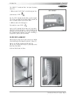
Страница 59: ...eating cooling operating setpoints The LED 3 indicates the current operating mode In Automatic mode i e in the programmed time schedules the LED flashes In forced occupied mode the LED is permanently on In forced unoccupied mode the LED is off Forced Occupied Key 4 Pressing this key will override the Automatic control and force the unit to run in its Occupied mode Whilst in this mode the LED 3 wil...

Страница 60: ...Figure 67 This display unit allows you to read and modify all the values of the variables or setpoints of the rooftop to which it is connected NOTE If your ROOFTOP already has a KP17 Comfort display connected see previous section simply disconnect it and connect this panel to the same location once completed re connect the KP17 It is not necessary to switch off the power to the CLIMATIC whilst the...

Страница 61: ...en the unit is powered up the KP02 software version number is displayed version 1 0 for example Display Test The display can only be tested for correct operation when the unit is powered up and by pressing on the 3 keys A M and simultaneously If the display is working correctly the following will be displayed All digits are properly displayed Communication Error If there is no communication betwee...

Страница 62: ...iable address see above When the address of the required setpoint appears pressing V will likewise display the current value To increase the setpoint press V while holding down the key at the same time The address will increase slowly by pressing intermittently or more quickly by keeping your finger on the key To go to a lower setpoint proceed as above but with the key as well as the V key The new...

Страница 63: ...February 31st but when you try to validate it will be ignored and the preceding value stored 3 POWER SUPPLY LED 7 figure 40 When lit the LED indicates that the machine is powered up 4 MODE LED 8 figure 40 This LED indicates the current operating mode In normal mode i e within the programmed schedules the LED flashes In forced day mode the LED is permanently on and in forced night mode the LED is o...

Страница 64: ...ng 5 Midday 6 Evening 7 BMS 0 7 C 009 Mode Day of the week Start of mode active for the Week End mode 1 7 C 010 Mode Hour Start of mode active for the modes Week End Night Morning Midday Evening 0 h h 22 h C 011 Mode Minute Start of mode active for the modes Week end Night Morning Midday Evening 0 m m 59 m C 012 Mode Day of the week End of mode active for the Week End mode 1 7 C 013 Mode Hour End ...

Страница 65: ... regulation zone Off The fan is on high speed On The fan is on low speed Off On C 028 Mode Force the noise reduction mode On 50 of the compressors are unloaded Off On C 029 Mode Force the operation mode Off On C 030 Command Force the low speed on fan blower supply Off Off On C 031 Command Force the fresh air damper in the closed position 0 fresh air Off Off On C 032 Command Force the fresh air dam...

Страница 66: ...0 10 100 2nd Level Mini Factory Maxi C 050 kp17 Mode Maximum limit for room temperature Day mode in c active for the mode Day 21 0 c 27 0 c 35 0 c C 051 kp17 Mode Minimum limit for room temperature Day mode in c active for the mode Day 8 0 c 17 0 c 21 0 c C 052 Room control Minimum operation time for a stage in seconds 25 s 180 s 1800 s C 053 Room control Temperature difference between the beginni...

Страница 67: ...it the control in free cooling is not authorized The fresh air damper is then positioned on the minimum setting 0 0 c 26 0 c 60 0 c C 071 Control limit Fresh air damper Minimum outdoor temperature limit in c If the outdoor temperature is lower than this limit the control in free cooling is not authorized The fresh air damper is then positioned on the minimum setting 0 0 c 5 0 c 30 0 c C 072 Fresh ...

Страница 68: ... If the mixed air temperature is lower than this threshold electric heat is activated 0 0 c 5 0 c 10 0 c C 085 Safety limit Air flow detection Threshold of pressure difference for the loss of pressure detection in pa If the pressure difference across the filters is lower than this threshold the safety is activated 0 pa 20 pa 1000 pa C 086 Safety limit Clogged filter detection Threshold of pressure...

Страница 69: ...and humidity of the master unit are communicated to the slave units 2 The room temperature and humidity are taken as the average of the active probes 0 2 C 097 Configuration Link Selection of exchange mode for outdoor temperature and humidity 0 Inactive 1 The outdoor temperature and humidity of the master unit are communicated to the slave units 2 The outdoor temperature and humidity are taken as ...

Страница 70: ...utput exchanger V 020 Input Signal Shift of the set point V 021 Input Pressure in pa Air flow Supply fan V 022 Input Signal in ppm Air quality sensor Co V 023 Input Pressure in b Compressor n 1 V 024 Input Pressure in b Compressor n 2 V 025 Input Pressure in b Compressor n 3 V 026 Input Pressure in b Compressor n 4 V 027 Output Supply fan V 028 Output Supply fan Command low speed V 029 Output Extr...

Страница 71: ... of a defect 7 activation of a defect condenser 8 ventilation no ready V 062 Statute Compressor n 2 0 not configured 1 option cooling only 2 option heat pump 3 defrost in progress 5 limit outside temperature or remote command active 6 activation of a defect 7 activation of a defect condenser 8 ventilation no ready V 063 Statute Compressor n 3 0 not configured 1 option cooling only 2 option heat pu...

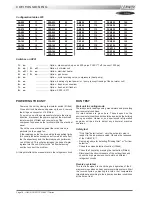
Страница 72: ...y V 083 Defects Memory Code V 084 Defects Memory Hour V 085 Defects Memory Minute V 086 Defects Memory Day V 087 Defects Memory Month V 088 Information Non standard program V 089 Information Number of version of the program USING THE KP02 MAINTENANCE CONTROL DISPLAY CONFIGURATION This information is taken into account by the program after having switched off on the CLIMATIC and a second time for C...

Страница 73: ...great power or pump except freezing of the hot water coil 6 on Option fresh air economiser 7 on Option fresh air all fresh air 8 on Option KP02 KP17 F A050 11 F A060 12 F A070 13 F A085 14 F A100 15 F A120 16 F A140 17 F A160 18 F A190 19 FXA025 20 FXA030 21 FXA035 22 FXA040 23 FXA055 24 FXA070 25 FXA085 26 FXA100 27 FXA110 28 FXA140 29 FXA170 30 F K050 111 F K060 112 F K070 113 F K085 114 F K100 ...

Страница 74: ...eters displayed in the various screens Recording of successive status of pre defined variables to create analog and event histories A KP07 unit can be attached to more than 8 LENNOX Rooftops providing they have the same software The link between the controllers and the display is serial and uses the JBUS protocol After being connected the unit tries to establish communication with the specified ma...

Страница 75: ... functions to them KEY ASSOCIATED ICON Selects the variable to be changed Selects the number to be changed By pressing successively on the key the cursor will move from digit to digit from right to left then the cursor remains on the last digit of the value to be changed Increases the number from 0 to 9 Confirms the current change Through MODIFICATION mode the user is able to choose the number of ...

Страница 76: ... customer Operational status Frost History Safety Errors Operational status Compressor n 1 Operational status Compressor n 2 Operational status Compressor n 3 Operational status Compressor n 4 Operational status Heaters History Safety Errors Hourmeters Electrical resistance History Safety Errors Hourmeters Humidifier History Sécurité défauts Hourmeters Compressors Hourmeters Fan Capacitors Measure...

Страница 77: ...Day Password Level 1 Settings Condition Weekend Settings On Ventilation Settings Condition Night Settings On Ventilation Settings Time Settings Condition Morning Settings On Ventilation Settings Time Settings Anticipation Settings Condition Noon Settings On Ventilation Settings Time Settings Condition Evening Settings On Ventilation Settings Time ...

Страница 78: ...ings Control Hot Settings Control Dehumidification Settings Control Humidification Settings Control Misc Settings Limits Ambient Settings Remote controls Settings Remote controls Settings Remote controls Password Level 2 Settings Limits Outside Settings Limits Blowing Settings Air flow Filters Settings Std order Ambient Settings Std order Blowing ...

Страница 79: ...humidity chart Flexy only Reset errors and error meters Go to error history Go to operation hourmeters Go to frosting component status Go to compressor and condenser operational status Go to heating devices operational status Go to humidifier operational status Flexy only Enter password Go to operational condition settings Go to control settings Go to safety settings Go to On Off and Discharge set...

Страница 80: ...Weekend Operating condition Night Operating condition Morning Operating condition Noon Operating condition Evening Operating condition BMS Operating status Cooling mode setting operation Heating mode setting operation Device in manual mode prohibited under control On Off Customer option On Off blower fan High Low Ventilation speed Flexy only Filters On Off Fresh air damper On Off Cold proportional...

Страница 81: ...cation interrupted between unit KP07 and a CPU board Start End 081 083 085 086 087 113 123 133 143 Faulty temperature sensors Start End 082 084 Faulty humidity sensors Flexy only Start End 112 122 132 142 Faulty pressure transmitters Flexy only Start End 013 022 096 Low temperature limit Start End 012 023 097 High temperature limit Start End 032 Low humidity limit Flexy only Start End 033 High hum...

Страница 82: ... 125 135 145 Faulty high pressure or faulty electrical compressor Start End 117 127 137 147 Faulty low pressure compressor Start End 092 093 Faulty condensers Start End 098 Faulty water flow Flexy only Start End 041 Faulty pump Flexy only Start End 011 Faulty electrical batteries Start End 014 015 Faulty gas burner Start End 031 Faulty humidifier Flexy only USING THE KP07 GRAPHIC CONTROL DISPLAY ...

Страница 83: ...reened cable only Limits of relays 10A 250V with resistive load 4A 250V with inductive load BMS VOLT FREE CONTACTS KIT DRY CONTACT KIT FOR BMS REMOTE SET POINT STOP CONTROL NIGHT CONTROL DAY CONTROL 50 LOAD SHEDDING HEAT LOAD SHEDDING COLD LOAD SHEDDING FAULT RESETTING FILTER FAULT TREATMENT FAN FAULT COMPRESSOR FAULT GAS BURNER FAULT ELECTRICAL RESISTANCE FAULT TOP LIMIT TEMPERATURE FAULT BOTTOM ...

Страница 84: ... and 04 for KP02 forced by the BMS contacts kit see this chapter forced by the computer connection The five available time slots are WEEK END NIGHT MORNING NOON EVENING If none of the time slots listed above is active the active slot is DAY A particular time slot BMS is activated if the unit is connected to a computer network 0 1 2 3 4 5 6 7 8 9 10 11 12 13 14 15 16 17 18 19 20 21 22 23 24 With th...

Страница 85: ...zone 26 ON forces low speed fan operation in the neutral zone 27 ON forces automatic low speed operation in heating zone 28 Low noise 29 Instruction used to force operation in the current setting CLIMATIC PARAMETERS The regulation zone is defined for a temperature less than the heating instruction or greater than the air conditioning instruction The neutral zone is between these 2 values NOTE The ...

Страница 86: ...GULATION OF AMBIENT AIR Two power factors one for cooling variable 72 the other for heating variable 73 are calculated according to the difference in temperature between the Setpoint and the reference temperature The progression of these cooling or heating power factors is limited by the temperature hysteresis and the activation differentials between 2 stages If the hysteresis value is 0 the power...

Страница 87: ...erential in heating setpoint 56 Inversion by setpoint 57 Hysteresis in heating setpoint 56 Gas 2 Gas 1 Gas 2 1 2 Gas 1 Gas 1 1 2 Gas 1 Cp1 Cp4 Compressor no 1 4 Hysteresis in air cond setpoint 53 Differential in air cond setpoint 54 Inertia zone Min fresh air Heating setpoint 16 Air conditioning setpoint 15 Damper 3 way valve or water coil ...

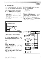
Страница 88: ...ulation by the air damper is to even out the temperature of supplied air to a value close to the average of the neutral zone This function is not taken into account if blowing regulation is active A power factor is calculated according to difference in temperature between the setpoint and the ambient and outside temperatures The progression of the power factor is limited by the maximum percentage ...

Страница 89: ...ygrometry is greater than the inside hygrometry the respective enthalpy values are then calculated According to the result obtained input of new air is optimised CLIMATIC PARAMETERS COMPRESSOR RELATED FUNCTIONS Anti short cycle The CLIMATIC provides protection of the compressors against frequent restarts This is why the compressors cannot be started even if requested to do so by regulation unless ...

Страница 90: ...ready on site NOTE In order to connect a unit fitted with CLIMATIC2 you must ensure that the program version is at least LF20 Otherwise it must be upgraded to LF20 before connection to Climalook 3 Climalook uses the internet explorer interface for local operation The local operating mode is completely automatic and does not require any configuration Like Climalink Climalook can receive remote quer...

Страница 91: ...USING INTERFACE 435 232 It is possible to connect up to 12 rooftops fitted with CLIMATIC 50 when using a Climalook 3 The connections between the units and the Climalink Climalook must be done using a double shielded pair of wire not supplied by Lennox This cable must have external metal braiding and its cross section must be at least 0 5mm2 with a maximum of 1mm2 The wires will be connected to eac...

Страница 92: ...MALINK CLIMALOOK SETTINGS FOR THE CONNECTIONS Depending on the version of Windows you are running access the Make new connection function Click on next Click on next Click Click Enter the telephone number to which your ClimaLook s modem is con nected Click ...

Страница 93: ...ain access to THE WELCOME PAGE First of all you must lower the virtual keyboard window before choosing the language NOTE To operate the program it is necessary to minimise the virtual keyboard Then click on the flag corresponding to the language you want to use Enter your access code and confirm The access code 999 serves as a temporary code until you have configured your own security code If your...

Страница 94: ... bottom of the page displays the unit currently being queried and can also be used to change the unit by clicking This takes you to the user page for the new machine If the unit does not exist is not powered up or if communication with it is impossible its icon disappears from the screen The program attemps to communicate with absent units every ten minutes It is possible modify several settings a...

Страница 95: ...HE SCHEDULE PAGE This page is used to display and modify all the configuration settings for each zone of a unit s operating schedule Use the refresh function to update the values read In addition it is possible to copy all the displayed settings and then paste them in another unit you have chosen The settings will only be modified if the submit function is confirmed For some settings a small icon ...

Страница 96: ...rs access codes This is a read only page The history is automatically cleared to ensure refreshment doesn t take too long This page will also show units faults To create a new user Click on name Click on Submit Select Entire site control interface CLIMALINK CLIMALOOK THE ACCESS PAGE This page enables users who have a third level access code to attribute access codes to other users The acccess code...

Страница 97: ...ink is functioning correctly after installation Connect up the unit and the KP14 Connect the cables to the J18 inputs on the Climatic boards After a few minutes the central unit should start its dialogue The LED on the Climatic board to the right of the J18 input should flash If this does not happen check the wiring The only way to examine the problem in more detail is to obtain a monitor and a mo...

Страница 98: ...refer to items not included in your scope of supply FUNCTIONS FCA FCK Cooling only unit 01 02 03 04 1 05 06 07 08 09 10FC 11 12 13 14 15 16 17 18 19 20 21 22 23 24 25 26 Electric heater TRIAC Hot water coil Economiser Extraction fan All fresh air Firestat Smoke detector Advanced control pack FC cooling FH heat pump Digital console KP02 Consoles KP07 or KP17 Hygiene probe Air sock control Dry conta...

Страница 99: ... 4 Adaptvision 01 02 03 04 1 05 06 07 08 09 10FH 11 12 13 14 15 16 17 18 19 20 21 22 23 24 25 26 Intelligent defrost FDA FDK Cooling only unit Heat pump Gas burner 33 60 kW Gas burner 120 kW Gas burner 180 kW Economiser Extraction fan All fresh air Firestat Smoke detector Advanced control pack FC cooling FH heat pump Digital console KP02 Consoles KP07 or KP17 Hygiene probe Air sock control Dry con...

Страница 100: ...ssor MG1 MG2 low pressure safety switch B53 B54 Compressor MG3 MG4 low pressure safety switch B61 B62 Compressor MG1 MG2 high pressure control switch B63 B64 Compressor MG3 MG4 high pressure control switch B71 B72 Condenser MC1 MC2 fan motor stoptherme B73 B74 Condenser MC3 MC4 fan motor stoptherme B81 B82 Scroll compressor MG1 MG2 protection module B83 B84 Scroll compressor MG3 MG4 protection mod...

Страница 101: ...sor MG3 MG4 contactor MP1 Circulation pump motor MR1 Economiser damper motor MR2 Blower damper motor MR3 Fresh air damper motor MR4 Extraction damper motor MR5 Recycler air damper motor MS1 MS2 Blower fan motor MS1 MS2 Q1 Q2 Blower fan motor MS1 MS2 protection Q5 Q6 Extraction fan motor ME1 ME2 protection Q9 Condenser MC1 MC2 fan motor protection Q10 Condenser MC3 MC4 fan motor protection Q11 Q12 ...

Страница 102: ...XA FXK Heat recovery unit MAIN CURRENT DIAGRAM Helicoid Helicoid Helicoid Helicoid Helicoid Helicoid Centrifugal Centrifugal Centrifugal Centrifugal Centrifugal Centrifugal Centrifugal Centrifugal ELECTRICAL DATA L3 L2 1112 12V H 12V G 12V E 12V F 5 5 kW 02 02 Helicoid Helicoid Helicoid Helicoid Helicoid Helicoid ...

Страница 103: ...ly unit with gas firesd heating FDA FDK Heat pump rooftopwith gas firesd heating MAIN CURRENT DIAGRAM Helicoid Centrifugal Helicoid Helicoid Helicoid Helicoid Helicoid Helicoid Helicoid Helicoid Helicoid Helicoid Helicoid Centrifugal Centrifugal Centrifugal Centrifugal Centrifugal ...

Страница 104: ...Page 102 IOM ROOF TOP FLEXY Series ELECTRICAL WIRING DIAGRAMS MAIN CURRENT DIAGRAM ...

Страница 105: ...IOM ROOF TOP FLEXY Series Page 103 ELECTRICAL WIRING DIAGRAMS MAIN CURRENT DIAGRAM Helicoid Centrifugal Centrifugal Helicoid Helicoid Helicoid ...

Страница 106: ...Page 104 IOM ROOF TOP FLEXY Series ELECTRICAL WIRING DIAGRAMS CLIMATIC CONTROLLER ...

Страница 107: ...IOM ROOF TOP FLEXY Series Page 105 ELECTRICAL WIRING DIAGRAMS CLIMATIC INPUT FC FH FX Confort Set Point GTC ...

Страница 108: ...Page 106 IOM ROOF TOP FLEXY Series ELECTRICAL WIRING DIAGRAMS CLIMATIC INPUT FG FD ...

Страница 109: ...IOM ROOF TOP FLEXY Series Page 107 ELECTRICAL WIRING DIAGRAMS CLIMATIC OUTPUT FC FH FX FAILURE HU ALARM ON TRANSFER STARTER PROGRESSIVE ...

Страница 110: ...Page 108 IOM ROOF TOP FLEXY Series ELECTRICAL WIRING DIAGRAMS ON TRANSFER STARTER PROGRESSIVE CLIMATIC OUTPUT FG FD ALARM FAILURE HU STARTER ...

Страница 111: ...IOM ROOF TOP FLEXY Series Page 109 ELECTRICAL WIRING DIAGRAMS WIRING DIAGRAM GAS BURNER 33 60 120 Kw ...

Страница 112: ...Page 110 IOM ROOF TOP FLEXY Series ELECTRICAL WIRING DIAGRAMS GAS BURNER 180 Kw ...

Страница 113: ...IOM ROOF TOP FLEXY Series Page 111 ELECTRICAL WIRING DIAGRAMS DAD SMOKE DETECTOR KP7 GRAPHIC DISPLAY RESISTANCE FEMELLE UNITES 2 3 4 5 6 7 8 CUSTOMER ELECTRICAL TRANSFO GRAPHIC CONTROL DISPLAY UNITE 1 ...

Страница 114: ...NTROL DAY CONTROL 50 LOAD SHEDDING HEAT LOAD SHEDDING COLD LOAD SHEDDING FAULT RESETTING FILTER FAULT TREATMENT FAN FAULT COMPRESSOR FAULT GAS BURNER FAULT ELECTRICAL RESISTANCE FAULT TOP LIMIT TEMPERATURE FAULT BOTTOM LIMIT TEMPERATURE FAULT HUMIDIFIER FAULT FILTER FAULT TREATMENT FAN FAULT COMPRESSOR FAULT GAS BURNER FAULT ELECTRICAL RESISTANCE FAULT ...

Страница 115: ...D2 Dialogue monitoring LED LD3 Power Fell monitoring LED LD4 Monitoring LED power 5V link SW1 Speed configuration 9600 4800 2400 or 1200 baud SW2 Speed configuration 9600 4800 2400 or 1200 baud SW3 TXD signal configuration RS232 position 2 3 RS485 position 1 2 SW4 RXD signal configuration RS232 position 2 3 RS485 position 1 2 SW5 10V Converter Position 1 2 U7 Programmable EPROM CL06 U9 Configurabl...

Страница 116: ...Page 114 IOM ROOF TOP FLEXY Series ELECTRICAL WIRING DIAGRAMS REPARTITEUR DE PHASES REPARTITEUR DE PHASES REPARTITEUR DE PHASES LAYOUT ELECTRICAL PANEL ...

Страница 117: ...IOM ROOF TOP FLEXY Series Page 115 ELECTRICAL WIRING DIAGRAMS LAYOUT ELECTRICAL PANEL FGA FDA 60 at 190 FGK FDK 60 at 190 ...

Страница 118: ...Page 116 IOM ROOF TOP FLEXY Series SITE ELECTRICAL CONNECTIONS KP02 KP18 E30 E32 KP18 E31 REGULATION TEMPERATURE PROBE HYGIENE PROBE REGULATION HYGROMETRY PROBE ...

Страница 119: ...ondenser system 2 094 Faulty condenser system 3 095 Faulty condenser system 4 096 Condenser water temperature too low 097 Condenser water overtemperature 098 Faulty condenser water flow 099 Error smoke 111 Faulty condenser temperature sensor compressor no 1 112 Faulty pressure transmitter compressor no 1 115 Faulty high pressure or faulty electrical power compressor no 1 117 Faulty low pressure co...

Страница 120: ...cycle will recommence normal operation for a temperature lower than 3 C below this setpoint 2nd Safety Level If the supply air temperature is greater than or equal to the setpoint C69 the safety system is activated The safety system automatically stops at a temperature lower than 3 C below this setpoint Supply Air Temperature Too Low 1st Safety Level If the supply air temperature is greater than o...

Страница 121: ... boxes the heat safety system is activated and stops the respective burner This safety system automatically cuts out on the CLIMATIC and the control unit must be manually reset Faulty Humidifier Flexy Only If there is a fault with the gas control unit for more than a minute the safety system is activated and stops the humidifier This safety system is automatically locked out In this case a manual ...

Страница 122: ...out In this case manual resetting is obligatory If a unit is fitted with an all or nothing servomotor powered damper the detection time extends to 2 minutes Flexy only Note This error is also displayed in the event of a shunt of the auxiliary contact of the contactor Faulty ventilation condenser circuit 1 or 2 The fan contactor is not connected although the CLIMATIC requests it The fan motor inter...

Страница 123: ...rs the condenser safety mechanism is applied The compressors are stopped This safety mechanism automatically cuts out if the loop temperature is less than 4 C from this setpoint It is also automatically locked out after 3 failures within a day In this case manual resetting is obligatory The counter is reset to zero every evening at 20 00 if its value does not exceed 3 failures Faulty Water Flow If...

Страница 124: ...safety system is activated and stops the compressor The safety system automatically cuts out after 4 minutes It is also automatically locked out after 3 failures within a day In this case manual resetting is obligatory The counter is reset to zero every evening at 20 00 if its value does not exceed 3 failures Faulty low pressure compressor If the low pressure pressostat is open and the compressor ...

Страница 125: ...il internal pressure drop between the liquid line and the suction line Good if 3bar Too high if 3bar coil blocked Stop the fan and create icing of the coil Check all circuits freeze evenly across the whole surface of the coil If some parts of the coil do not freeze this could indicate a problem with the distribution Change filter drier Attempt to free the valve adjusting element by freezing the va...

Страница 126: ...erant and vacuum the circuit Ensure very low and slow vacuum for R407c Recharge the unit Check the condenser coil and clean is necessary Check clearance around the condenser Refer to LP problems and LP cut out section Open the superheat adjustment on the expan sion valve Check the pressure drop on the filter drier in the suction line Check operation of the valve by going through cycle inversions C...

Страница 127: ...heck that the Klixon is positioned in the airflow relocate Klixon if necessary Check that there is no heat transfer from the Klixon support ELECTRIC HEATER FAULT Water found in the ventilation section Water ingress in the filter compartment POSSIBLE CAUSE AND SYMPTOMS Cooling mode Water carried away from the coil because of excessive airflow and speed on the coil Low air pressure in the compartmen...

Страница 128: ...llow such a plan to keep a rooftop unit in good working order Regular maintenance of your rooftop will extend its operating life and reduce operating faults Symbols and Legend 0 Operation which can be carried out by on site maintenance technicians Operation which must be carried out by qualified personnel trained to operate on this type of equipment NOTE Times are given for information purpose onl...

Страница 129: ...r life but may need replacement after 10000 hours Check absorbed Amps on all three phases compare with the nominal value given in the electrical wiring diagram Start the unit Trigger the smoke detector by moving a magnet around the detector head Reset unit and control Refer to the commissioning sheet Check all set points are set according to this document Check the time and date of the control Che...

Страница 130: ...ly check the coils for dirt If not too dirty cleaning with a light brush may be enough WARNING Fins and copper tubes are very fragile Any damage WILL reduce the performances of the unit If very dirty deep industrial cleaning is required using de greasing agents External contractors must be called Isolate the unit Pull the electric heater out of the heater module box and check the resistances fo tr...

Страница 131: ...nvironment which is known to be corrosive unless a special protective coating has been applied by the owner for these applications which has been recommended by a competent body not linked to the owner and after carrying out a study of the site Note With the exception of the casing the rest of the machine is covered by the warranty of our general terms of sale DO NOT CONFUSE THE WARRANTY WITH MAIN...

Страница 132: ...Page 130 IOM ROOF TOP FLEXY Series ISO 9001 CERTIFICATION ...

Страница 133: ...IOM ROOF TOP FLEXY Series Page 131 PED CERTIFICATION OF CONFORMITY ...

Страница 134: ...Page 132 IOM ROOF TOP FLEXY Series GLASS WOOL FIRE CLASS ...

Страница 135: ...IOM ROOF TOP FLEXY Series Page 133 33 kW GAS BURNER CE CERTIFICATION OF CONFORMITY ...

Страница 136: ...Page 134 IOM ROOF TOP FLEXY Series 60 kW GAS BURNER CE CERTIFICATION OF CONFORMITY ...

Страница 137: ...IOM ROOF TOP FLEXY Series Page 135 120 kW GAS BURNER CE CERTIFICATION OF CONFORMITY ...

Страница 138: ...Page 136 IOM ROOF TOP FLEXY Series 180 kW GAS BURNER CE CERTIFICATION OF CONFORMITY ...

Страница 139: ...IOM ROOF TOP FLEXY Series Page 137 INSULATION FIRE CLASS ...

Страница 140: ...Page 138 IOM ROOF TOP FLEXY Series INSULATION FIRE CLASS ...

Страница 141: ......

Страница 142: ...471 800 fax 31 33 2459 220 e mail info lennoxbenelux com LENNOX POLSKA Sp zo o tel 48 22 832 26 61 fax 48 22 832 26 62 e mail info lennoxpolska pl LENNOX PORTUGALLDA tel 351 22 998 33 70 fax 351 22 998 33 79 e mail info lennoxportugal com LENNOX DISTRIBUTION MOSCOW tel 7 095 246 07 46 fax 7 502 933 29 55 e mail lennox dist moscow netmaster ru LENNOX SLOVENSKOs r o tel 421 2 44 87 19 27 fax 421 2 4...

Отзывы: