IOM / ROOF-TOP FLEXY™ Series - Page 127
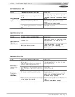
MAINTENANCE PLAN
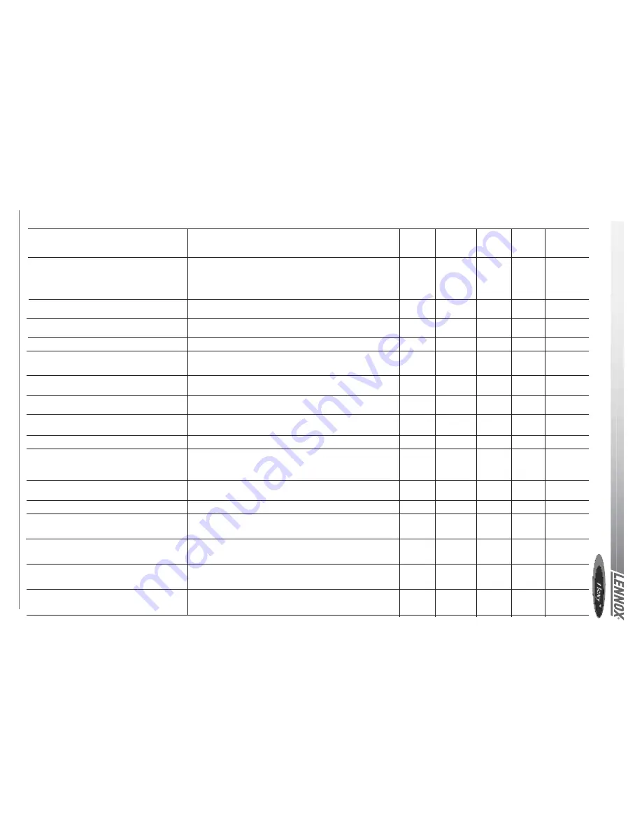
TASK
Clean or replace filters: Disposable, or metal
frame.
Visual check of the oil level
Position check of the compressor crankcase
heater.
Belt tension check.
Centrifugal fan bearings check
Check absorbed Amps
Check Smoke detector
Check Climatic control, set-points and varia-
bles
Check clock settings
Check the position and tightness of
refrigeration components
Check Airflow rate safety switch (if fitted).
Check freeze protection on HWC
Check three way valve on HWC
Check economiser actuator operation
Check refrigeration 4way valve
Check tightness of all electrical connections
OPERATING MODE
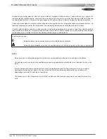
Replace filters with new ones if disposable. Vacuum clean or blow
the dirt. Wash and dry carefully. +Replace media if necessary
Blocked filter will reduced the performance of the unit.
THE UNIT MUST NOT OPERATE WITHOUT FILTERS
Visually check the oil level through the sight glass on the side of
the compressor casing
Check the heating resistance is fitted properly and tight around the
compressor body.
Check belt tension (Info in IOM) Replace belt if necessary.
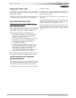
Isolate unit from the main power supply; Push the fan wheel
manually and check for abnormal noises. Bearings are lubricated
for life but may need replacement after 10000 hours
Check absorbed Amps on all three phases; compare with the
nominal value given in the electrical wiring diagram.
Start the unit. Trigger the smoke detector by moving a magnet
around the detector head. Reset unit and control.
Refer to the commissioning sheet; Check all set points are set
according to this document.
Check the time and date of the control
Check systematically all connections and fixings on the
refrigeration circuit. Check for oil traces, eventually a leak test
should be conducted. Check operating pressures correspond to
the ones indicated on the commissioning sheet
Shut down supply fan. The fault must be detected within 5
seconds.
Increase room set-point 10°C above the actual room temperature.
Check operation of the piston. It must move away from the valve
head. Reset the control.
Check all fixings and transmission. Stop the unit using the control.
The fresh air damper must closes. Start the unit the fresh air
damper should open
With the unit running in cooling mode increase the room set-point
temperature by 10°C. The unit should switch to heat pump mode.
Reset the control.
Power down the unit and check and tighten all screws, terminal
and electric connections, taking a particular attention to the power
lines and low voltage control wires
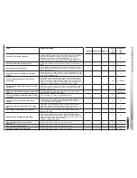
6
YEARLY
ESTIMATED
MONTHLY QUARTERLY MONTHLY
B4
TIME
WINTER
(mn)
0
20
0
2
0
2
0
10
0
10
∆
15
∆
5
∆
15
0
5
∆
30
0
∆
5
∆
5
∆
5
∆
5
∆
30
Table 16
Содержание ROOFTOP FLEXY FCA 100
Страница 1: ...INSTALLATION OPERATING MAINTENANCE MANUAL ROOFTOP FLEXY English August 2003 ...
Страница 2: ......
Страница 33: ...IOM ROOF TOP FLEXY Series Page 31 AIR FLOW BALANCING AT 12 12 FAN ...
Страница 34: ...Page 32 IOM ROOF TOP FLEXY Series AIR FLOW BALANCING AT 15 15 FAN ...
Страница 35: ...IOM ROOF TOP FLEXY Series Page 33 AIR FLOW BALANCING AT 18 13 ...
Страница 36: ...Page 34 IOM ROOF TOP FLEXY Series AIR FLOW BALANCING AT 18 18 FAN ...
Страница 37: ...IOM ROOF TOP FLEXY Series Page 35 AIR FLOW BALANCING RDN 450 FAN ...
Страница 38: ...Page 36 IOM ROOF TOP FLEXY Series AIR FLOW BALANCING ADN 355 FAN ...
Страница 39: ...IOM ROOF TOP FLEXY Series Page 37 AIR FLOW BALANCING ADN 400 FAN ...
Страница 40: ...Page 38 IOM ROOF TOP FLEXY Series AIR FLOW BALANCING ADN 450 FAN ...
Страница 56: ...Page 54 IOM ROOF TOP FLEXY Series GAS BURNERS 60 KW BURNER FOR FGX 60 AND 70 MODELS 1 2 Figure 63 ...
Страница 57: ...IOM ROOF TOP FLEXY Series Page 55 GAS BURNER 120 KW BURNER FOR FGX 60 70 AND 100 MODELS 1 2 3 Figure 64 ...
Страница 58: ...Page 56 IOM ROOF TOP FLEXY Series 180 KW BURNER FOR FGX 120 AND 140 MODELS GAS BURNER 1 2 3 Figure 65 ...
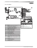
Страница 104: ...Page 102 IOM ROOF TOP FLEXY Series ELECTRICAL WIRING DIAGRAMS MAIN CURRENT DIAGRAM ...
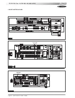
Страница 106: ...Page 104 IOM ROOF TOP FLEXY Series ELECTRICAL WIRING DIAGRAMS CLIMATIC CONTROLLER ...
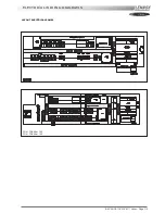
Страница 107: ...IOM ROOF TOP FLEXY Series Page 105 ELECTRICAL WIRING DIAGRAMS CLIMATIC INPUT FC FH FX Confort Set Point GTC ...
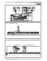
Страница 108: ...Page 106 IOM ROOF TOP FLEXY Series ELECTRICAL WIRING DIAGRAMS CLIMATIC INPUT FG FD ...
Страница 111: ...IOM ROOF TOP FLEXY Series Page 109 ELECTRICAL WIRING DIAGRAMS WIRING DIAGRAM GAS BURNER 33 60 120 Kw ...
Страница 112: ...Page 110 IOM ROOF TOP FLEXY Series ELECTRICAL WIRING DIAGRAMS GAS BURNER 180 Kw ...
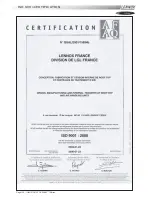
Страница 132: ...Page 130 IOM ROOF TOP FLEXY Series ISO 9001 CERTIFICATION ...
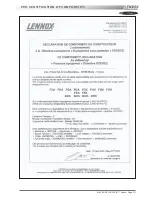
Страница 133: ...IOM ROOF TOP FLEXY Series Page 131 PED CERTIFICATION OF CONFORMITY ...
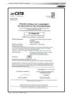
Страница 134: ...Page 132 IOM ROOF TOP FLEXY Series GLASS WOOL FIRE CLASS ...
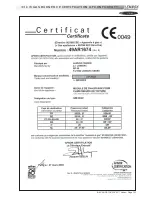
Страница 135: ...IOM ROOF TOP FLEXY Series Page 133 33 kW GAS BURNER CE CERTIFICATION OF CONFORMITY ...
Страница 136: ...Page 134 IOM ROOF TOP FLEXY Series 60 kW GAS BURNER CE CERTIFICATION OF CONFORMITY ...
Страница 137: ...IOM ROOF TOP FLEXY Series Page 135 120 kW GAS BURNER CE CERTIFICATION OF CONFORMITY ...
Страница 138: ...Page 136 IOM ROOF TOP FLEXY Series 180 kW GAS BURNER CE CERTIFICATION OF CONFORMITY ...
Страница 139: ...IOM ROOF TOP FLEXY Series Page 137 INSULATION FIRE CLASS ...
Страница 140: ...Page 138 IOM ROOF TOP FLEXY Series INSULATION FIRE CLASS ...
Страница 141: ......

