

Page 18 - IOM / ROOF-TOP FLEXY™ Series
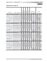
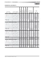
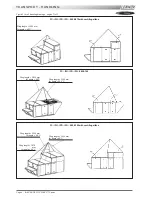
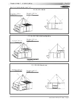
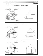
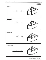
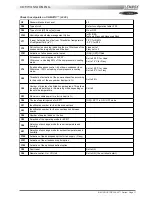
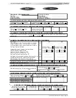
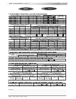
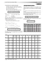
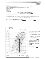
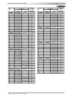
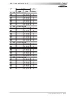
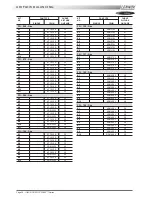
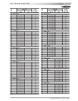
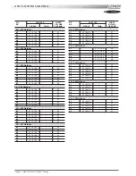
Configuration table LF20
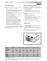
COMMISSIONING
F.A050
11
F.A060
12
F.A070
13
F.A085
14
F.A100
15
F.A120
16
F.A140
17
F.A160
18
F.A190
19
FXA025
20
FXA030
21
FXA035
22
FXA040
23
FXA055
24
FXA070
25
FXA085
26
FXA100
27
FXA110
28
FXA140
29
FXA170
30
F.K050
111
F.K060
112
F.K070
113
F.K085
114
F.K100
115
F.K120
116
F.K140
117
F.K160
118
F.K190
119
FXK025
120
FXK030
121
FXK035
122
FXK040
123
FXK055
124
FXK070
125
FXK085
126
FXK100
127
FXK110
128
FXK140
129
FXK170
130
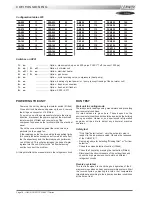
Switches on KP01
1 =
on
....................... Option : pressure pick-up on air 500 pa (on FLEXY™ off = sensor 1000 pa)
2 =
on | 3 =
off
................... Option : hot water coil
2 =
off | 3 =
on
................... Option : electrical heater
2 =
on | 3 =
on
................... Option : gas burner
4 =
on
....................... Option : cycle reversing valve, compressors (heat pump)
5 =
on
....................... Option : heating of great power / or / pump (except freezing of the hot water coil)
6 =
on
....................... Option : fresh air, economiser
7 =
on
....................... Option : fresh air, all fresh air
8 =
on
....................... Option : KP02 / KP17
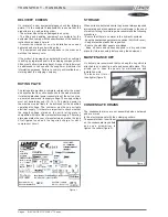
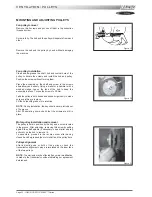
POWERING THE UNIT
- Power up the unit by closing the isolator switch (if fitted).
- Close all circuit breakers and power up the unit, remove
the bridge on connector J14 if fitted.
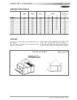
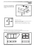
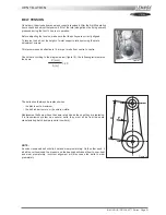
- If now only one of the components rotates in the wrong
direction, disconnect the power supply at the machine's
isolator switch (if fitted) and reverse two of the
component's phases on the terminal within the electrical
panel.
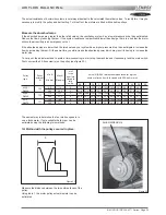
- Check the current drawn against the rated values, in
particular on the supply fan.
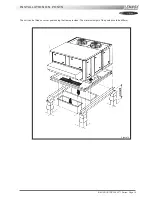
- If the readings on the fan are outside the specified limits,
this usually indicates excessive air flow which will affect
the life expectancy and the thermodynamic performan-
ces of the unit. This will also increase the risks of water
ingress into the unit. Refer to the "air flow balancing"
section to correct the problem.
At this point attach the manometers to the refrigerant circuit.
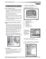
RUN TEST
Start unit in cooling mode
Thermodynamic readings using manometers and prevailing
environmental conditions.
No rated values are given here. These depend on the
environmental conditions both outside and inside the building
during operation. However, an experienced refrigeration
engineer will be able to detect any abnormal machine
operation.
Safety test
- "Dirty filter" detection test : vary the set-point value in
respect to the air pressure value. Observe the response
of the CLIMATIC™.
- Same procedure for detecting "Missing filter" or "Air flow
detection".
- Check the smoke detection function (if fitted).
- Check the Firestat by pressing the test button(if fitted).
- Disconnect the circuit breakers of the outdoor fans and
check the high pressure cut-out points on different
refrigerant circuits.
Reverse cycle test
This test is designed to check the good operation of the 4-
way reversing valves on heat pump reversible systems. Start
the reverse cycle by adjusting the cold or hot temperature
threshold data according to the indoor and outdoor conditions
at the time of test.
Содержание ROOFTOP FLEXY FCA 100
Страница 1: ...INSTALLATION OPERATING MAINTENANCE MANUAL ROOFTOP FLEXY English August 2003 ...
Страница 2: ......
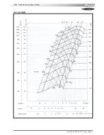
Страница 33: ...IOM ROOF TOP FLEXY Series Page 31 AIR FLOW BALANCING AT 12 12 FAN ...
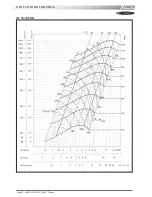
Страница 34: ...Page 32 IOM ROOF TOP FLEXY Series AIR FLOW BALANCING AT 15 15 FAN ...
Страница 35: ...IOM ROOF TOP FLEXY Series Page 33 AIR FLOW BALANCING AT 18 13 ...
Страница 36: ...Page 34 IOM ROOF TOP FLEXY Series AIR FLOW BALANCING AT 18 18 FAN ...
Страница 37: ...IOM ROOF TOP FLEXY Series Page 35 AIR FLOW BALANCING RDN 450 FAN ...
Страница 38: ...Page 36 IOM ROOF TOP FLEXY Series AIR FLOW BALANCING ADN 355 FAN ...
Страница 39: ...IOM ROOF TOP FLEXY Series Page 37 AIR FLOW BALANCING ADN 400 FAN ...
Страница 40: ...Page 38 IOM ROOF TOP FLEXY Series AIR FLOW BALANCING ADN 450 FAN ...
Страница 56: ...Page 54 IOM ROOF TOP FLEXY Series GAS BURNERS 60 KW BURNER FOR FGX 60 AND 70 MODELS 1 2 Figure 63 ...
Страница 57: ...IOM ROOF TOP FLEXY Series Page 55 GAS BURNER 120 KW BURNER FOR FGX 60 70 AND 100 MODELS 1 2 3 Figure 64 ...
Страница 58: ...Page 56 IOM ROOF TOP FLEXY Series 180 KW BURNER FOR FGX 120 AND 140 MODELS GAS BURNER 1 2 3 Figure 65 ...
Страница 104: ...Page 102 IOM ROOF TOP FLEXY Series ELECTRICAL WIRING DIAGRAMS MAIN CURRENT DIAGRAM ...
Страница 106: ...Page 104 IOM ROOF TOP FLEXY Series ELECTRICAL WIRING DIAGRAMS CLIMATIC CONTROLLER ...
Страница 107: ...IOM ROOF TOP FLEXY Series Page 105 ELECTRICAL WIRING DIAGRAMS CLIMATIC INPUT FC FH FX Confort Set Point GTC ...
Страница 108: ...Page 106 IOM ROOF TOP FLEXY Series ELECTRICAL WIRING DIAGRAMS CLIMATIC INPUT FG FD ...
Страница 111: ...IOM ROOF TOP FLEXY Series Page 109 ELECTRICAL WIRING DIAGRAMS WIRING DIAGRAM GAS BURNER 33 60 120 Kw ...
Страница 112: ...Page 110 IOM ROOF TOP FLEXY Series ELECTRICAL WIRING DIAGRAMS GAS BURNER 180 Kw ...
Страница 132: ...Page 130 IOM ROOF TOP FLEXY Series ISO 9001 CERTIFICATION ...
Страница 133: ...IOM ROOF TOP FLEXY Series Page 131 PED CERTIFICATION OF CONFORMITY ...
Страница 134: ...Page 132 IOM ROOF TOP FLEXY Series GLASS WOOL FIRE CLASS ...
Страница 135: ...IOM ROOF TOP FLEXY Series Page 133 33 kW GAS BURNER CE CERTIFICATION OF CONFORMITY ...
Страница 136: ...Page 134 IOM ROOF TOP FLEXY Series 60 kW GAS BURNER CE CERTIFICATION OF CONFORMITY ...
Страница 137: ...IOM ROOF TOP FLEXY Series Page 135 120 kW GAS BURNER CE CERTIFICATION OF CONFORMITY ...
Страница 138: ...Page 136 IOM ROOF TOP FLEXY Series 180 kW GAS BURNER CE CERTIFICATION OF CONFORMITY ...
Страница 139: ...IOM ROOF TOP FLEXY Series Page 137 INSULATION FIRE CLASS ...
Страница 140: ...Page 138 IOM ROOF TOP FLEXY Series INSULATION FIRE CLASS ...
Страница 141: ......


