Page 12 - IOM / ROOF-TOP FLEXY™ Series
PRELIMINARY CHECK
Before installing the equipment, the following items MUST be
checked :
- Is there sufficient space for the equipment?
- Is the surface on which the equipment is to be installed
sufficiently solid to withstand its weight ? A detailed
study of the frame must be made beforehand.
- Do the supply and return ductwork openings excessively
weaken the structure?
- Are there any obstructing items which could hinder the
operation of the equipment?
- Does the electrical power available correspond to the
equipment's electrical specifications?
- Is drainage provided for the condensate?
- Is there sufficient access for maintenance?
- Installation of the equipment could require different
lifting methods which may vary with each installation
(helicopter or crane). Have these been evaluated ?
- Ensure that the unit is installed in accordance with the
installation instructions and applicable codes.
- Check to ensure that the refrigerant lines do not rub
against the cabinet or against other refrigerant lines.
In general, make sure no obstacles (walls, trees or roof ledges)
are obstructing the duct connections or hindering assembly
and maintenance access.
INSTALLATION
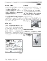
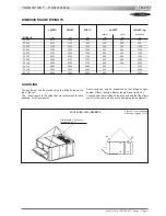
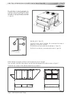
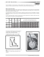
Figure 5
INSTALLATION REQUIREMENTS
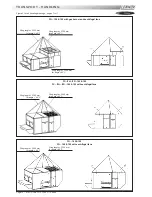
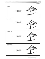
The surface on which the equipment is to be installed must
be clean and free of any obstacles which could hinder the
flow of air to the condensers:
- Avoid uneven surfaces
- Avoid installing two units side by side or close to each
other as this may restrict the airflow to the condensers.
Before installing a packaged rooftop unit it is important to
understand :
- The direction of prevailing winds.
- The direction and position of air flows.
- The external dimensions of the unit and the dimensions
of the supply and return air connections.
- The arrangement of the doors and the space required to
open them to access the various components.
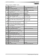
Figure 5 shows the required clearances and dimensions.
CONNECTIONS
- Ensure that all the pipework crossing walls or roofs are
secured and insulated.
- To avoid condensation problems, be sure all pipes are
insulated according to temperatures of fluids and type of
rooms.
NOTE : The AQUILUX protection sheets fitted to the finned
surfaces must be removed prior to start up.
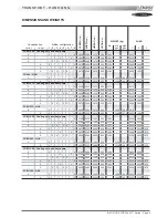
MODELS
A
B
C
D
FC/FH/FG/FD
60
!
!
!
!
!
140
1400
2000
1400
2300
160 & 190
2000
2000
2000
2300
FX
25 & 30
*
1100
*
1700
35
!
!
!
!
!
55
*
1300
*
2300
70
!
!
!
!
!
100
*
1700
*
2300
110
!
!
!
!
!
170
*
2000
*
2300
* : according to connection
Содержание ROOFTOP FLEXY FCA 100
Страница 1: ...INSTALLATION OPERATING MAINTENANCE MANUAL ROOFTOP FLEXY English August 2003 ...
Страница 2: ......
Страница 33: ...IOM ROOF TOP FLEXY Series Page 31 AIR FLOW BALANCING AT 12 12 FAN ...
Страница 34: ...Page 32 IOM ROOF TOP FLEXY Series AIR FLOW BALANCING AT 15 15 FAN ...
Страница 35: ...IOM ROOF TOP FLEXY Series Page 33 AIR FLOW BALANCING AT 18 13 ...
Страница 36: ...Page 34 IOM ROOF TOP FLEXY Series AIR FLOW BALANCING AT 18 18 FAN ...
Страница 37: ...IOM ROOF TOP FLEXY Series Page 35 AIR FLOW BALANCING RDN 450 FAN ...
Страница 38: ...Page 36 IOM ROOF TOP FLEXY Series AIR FLOW BALANCING ADN 355 FAN ...
Страница 39: ...IOM ROOF TOP FLEXY Series Page 37 AIR FLOW BALANCING ADN 400 FAN ...
Страница 40: ...Page 38 IOM ROOF TOP FLEXY Series AIR FLOW BALANCING ADN 450 FAN ...
Страница 56: ...Page 54 IOM ROOF TOP FLEXY Series GAS BURNERS 60 KW BURNER FOR FGX 60 AND 70 MODELS 1 2 Figure 63 ...
Страница 57: ...IOM ROOF TOP FLEXY Series Page 55 GAS BURNER 120 KW BURNER FOR FGX 60 70 AND 100 MODELS 1 2 3 Figure 64 ...
Страница 58: ...Page 56 IOM ROOF TOP FLEXY Series 180 KW BURNER FOR FGX 120 AND 140 MODELS GAS BURNER 1 2 3 Figure 65 ...
Страница 104: ...Page 102 IOM ROOF TOP FLEXY Series ELECTRICAL WIRING DIAGRAMS MAIN CURRENT DIAGRAM ...
Страница 106: ...Page 104 IOM ROOF TOP FLEXY Series ELECTRICAL WIRING DIAGRAMS CLIMATIC CONTROLLER ...
Страница 107: ...IOM ROOF TOP FLEXY Series Page 105 ELECTRICAL WIRING DIAGRAMS CLIMATIC INPUT FC FH FX Confort Set Point GTC ...
Страница 108: ...Page 106 IOM ROOF TOP FLEXY Series ELECTRICAL WIRING DIAGRAMS CLIMATIC INPUT FG FD ...
Страница 111: ...IOM ROOF TOP FLEXY Series Page 109 ELECTRICAL WIRING DIAGRAMS WIRING DIAGRAM GAS BURNER 33 60 120 Kw ...
Страница 112: ...Page 110 IOM ROOF TOP FLEXY Series ELECTRICAL WIRING DIAGRAMS GAS BURNER 180 Kw ...
Страница 132: ...Page 130 IOM ROOF TOP FLEXY Series ISO 9001 CERTIFICATION ...
Страница 133: ...IOM ROOF TOP FLEXY Series Page 131 PED CERTIFICATION OF CONFORMITY ...
Страница 134: ...Page 132 IOM ROOF TOP FLEXY Series GLASS WOOL FIRE CLASS ...
Страница 135: ...IOM ROOF TOP FLEXY Series Page 133 33 kW GAS BURNER CE CERTIFICATION OF CONFORMITY ...
Страница 136: ...Page 134 IOM ROOF TOP FLEXY Series 60 kW GAS BURNER CE CERTIFICATION OF CONFORMITY ...
Страница 137: ...IOM ROOF TOP FLEXY Series Page 135 120 kW GAS BURNER CE CERTIFICATION OF CONFORMITY ...
Страница 138: ...Page 136 IOM ROOF TOP FLEXY Series 180 kW GAS BURNER CE CERTIFICATION OF CONFORMITY ...
Страница 139: ...IOM ROOF TOP FLEXY Series Page 137 INSULATION FIRE CLASS ...
Страница 140: ...Page 138 IOM ROOF TOP FLEXY Series INSULATION FIRE CLASS ...
Страница 141: ......


