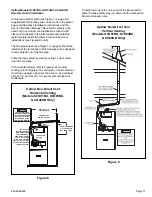
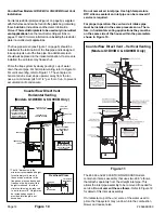
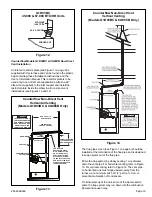
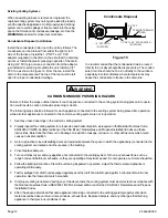
background image

# 45466K003

Page 8

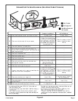
Figure 4

Sidewall Vent Terminal Clearances (Direct Vented Furnaces)

1

In accordance with the current 

CSA B149.1, Natural Gas and

Propane Installation Code

2

In accordance with the current 

ANSI Z2223.1/NFPA 54, National

Fuel Gas Code

A vent shall not terminate directly above a sidewalk or paved

driveway that is located between two single family dwellings and

serves both dwellings.

Permitted only if veranda, porch, deck, or balcony is fully open on a

minimum of two sides beneath the floor.

* For clearances not specified in 

ANSI Z2223.1/NFPA 54 

or

 CSA

B149.1

, the following statement shall be included:

Clearance in accordance with local installation codes and the

requirements of the gas supplier and the manufacturer

s installation

instructions.

V

X

Vent Terminal

Air Supply Inlet

Area Where Terminal Is
Not Permitted

s

n

o

i

t

a

l

l

a

t

s

n

I

n

a

i

d

a

n

a

C

1

s

n

o

i

t

a

l

l

a

t

s

n

I

S

U

2

A

y

n

o

c

l

a

b

r

o

,

k

c

e

d

,

h

c

r

o

p

,

a

d

n

a

r

e

v

,

e

d

a

r

g

e

v

o

b

a

e

c

n

a

r

a

e

l

C

)

m

c

0

3

(

s

e

h

c

n

i

2

1

)

m

c

0

3

(

s

e

h

c

n

i

2

1

B

d

e

n

e

p

o

e

b

y

a

m

t

a

h

t

r

o

o

d

r

o

w

o

d

n

i

w

o

t

e

c

n

a

r

a

e

l

C

<

s

e

c

n

a

il

p

p

a

r

o

f

)

m

c

5

1

(

s

e

h

c

n

i

6

0

3

(

s

e

h

c

n

i

2

1

,

)

W

k

3

(

h

u

t

B

0

0

0

,

0

1

3

(

h

u

t

B

0

0

0

,

0

1

>

s

e

c

n

a

il

p

p

a

r

o

f

)

m

c

,

)

W

k

0

3

(

h

u

t

B

0

0

0

,

0

0

1

<

d

n

a

,

)

W

k

>

s

e

c

n

a

il

p

p

a

r

o

f

)

m

c

1

9

(

s

e

h

c

n

i

6

3

)

W

k

0

3

(

h

u

t

B

0

0

0

,

0

0

1

<

s

e

c

n

a

il

p

p

a

r

o

f

)

m

c

5

1

(

s

e

h

c

n

i

6

3

2

(

s

e

h

c

n

i

9

,

)

W

k

3

(

h

u

t

B

0

0

0

,

0

1

h

u

t

B

0

0

0

,

0

1

>

s

e

c

n

a

il

p

p

a

r

o

f

)

m

c

5

1

(

h

u

t

B

0

0

0

,

0

5

<

d

n

a

,

)

W

k

3

(

r

o

f

)

m

c

0

3

(

s

e

h

c

n

i

2

1

,

)

W

k

)

W

k

5

1

(

h

u

t

B

0

0

0

,

0

5

>

s

e

c

n

a

il

p

p

a

C

w

o

d

n

i

w

d

e

s

o

l

c

y

l

t

n

e

n

a

m

r

e

p

o

t

e

c

n

a

r

a

e

l

C

*

*

D

e

h

t

e

v

o

b

a

d

e

t

a

c

o

l

t

i

f

f

o

s

d

e

t

a

li

t

n

e

v

o

t

e

c

n

a

r

a

e

l

c

l

a

c

i

t

r

e

V

e

h

t

m

o

r

f

)

m

c

1

6

(

t

e

e

f

2

f

o

e

c

n

a

t

s

i

d

l

a

t

n

o

z

i

r

o

h

a

n

i

h

t

i

w

l

a

n

i

m

r

e

t

l

a

n

i

m

r

e

t

e

h

t

f

o

e

n

il

r

e

t

n

e

c

*

*

E

t

i

f

f

o

s

d

e

t

a

li

t

n

e

v

n

u

o

t

e

c

n

a

r

a

e

l

C

*

*

F

r

e

n

r

o

c

e

d

i

s

t

u

o

o

t

e

c

n

a

r

a

e

l

C

*

*

G

r

e

n

r

o

c

e

d

i

s

n

i

o

t

e

c

n

a

r

a

e

l

C

*

*

H

e

v

o

b

a

d

e

d

n

e

t

x

e

e

n

il

r

e

t

n

e

c

f

o

e

d

i

s

h

c

a

e

o

t

e

c

n

a

r

a

e

l

C

y

l

b

m

e

s

s

a

r

o

t

a

l

u

g

e

r

/

r

e

t

e

m

5

1

t

h

g

i

e

h

a

n

i

h

t

i

w

)

m

c

1

9

(

t

e

e

f

3

e

h

t

e

v

o

b

a

)

m

5

.

4

(

t

e

e

f

y

l

b

m

e

s

s

a

r

o

t

a

l

u

g

e

r

/

r

e

t

e

m

*

I

t

e

l

t

u

o

t

n

e

v

r

o

t

a

l

u

g

e

r

e

c

i

v

r

e

s

o

t

e

c

n

a

r

a

e

l

C

)

m

c

1

9

(

t

e

e

f

3

*

J

e

h

t

r

o

g

n

i

d

li

u

b

o

t

t

e

l

n

i

y

l

p

p

u

s

r

i

a

l

a

c

i

n

a

h

c

e

m

n

o

n

o

t

e

c

n

a

r

a

e

l

C

e

c

n

a

il

p

p

a

r

e

h

t

o

y

n

a

o

t

t

e

l

n

i

r

i

a

n

o

i

t

s

u

b

m

o

c

<

s

e

c

n

a

il

p

p

a

r

o

f

)

m

c

5

1

(

s

e

h

c

n

i

6

0

3

(

s

e

h

c

n

i

2

1

,

)

W

k

3

(

h

u

t

B

0

0

0

,

0

1

3

(

h

u

t

B

0

0

0

,

0

1

>

s

e

c

n

a

il

p

p

a

r

o

f

)

m

c

,

)

W

k

0

3

(

h

u

t

B

0

0

0

,

0

0

1

<

d

n

a

,

)

W

k

>

s

e

c

n

a

il

p

p

a

r

o

f

)

m

c

1

9

(

s

e

h

c

n

i

6

3

)

W

k

0

3

(

h

u

t

B

0

0

0

,

0

0

1

<

s

e

c

n

a

il

p

p

a

r

o

f

)

m

c

5

1

(

s

e

h

c

n

i

6

3

2

(

s

e

h

c

n

i

9

,

)

W

k

3

(

h

u

t

B

0

0

0

,

0

1

h

u

t

B

0

0

0

,

0

1

>

s

e

c

n

a

il

p

p

a

r

o

f

)

m

c

5

1

(

h

u

t

B

0

0

0

,

0

5

<

d

n

a

,

)

W

k

3

(

r

o

f

)

m

c

0

3

(

s

e

h

c

n

i

2

1

,

)

W

k

)

W

k

5

1

(

h

u

t

B

0

0

0

,

0

5

>

s

e

c

n

a

il

p

p

a

K

t

e

l

n

i

y

l

p

p

u

s

r

i

a

l

a

c

i

n

a

h

c

e

m

a

o

t

e

c

n

a

r

a

e

l

C

)

m

3

8

.

1

(

t

e

e

f

6

0

1

n

i

h

t

i

w

f

i

e

v

o

b

a

)

m

c

1

9

(

t

e

e

f

3

y

ll

a

t

n

o

z

i

r

o

h

)

m

3

(

t

e

e

f

L

d

e

t

a

c

o

l

y

a

w

e

v

i

r

d

d

e

v

a

p

r

o

k

l

a

w

e

d

i

s

d

e

v

a

p

e

v

o

b

a

e

c

n

a

r

a

e

l

C

y

t

r

e

p

o

r

p

c

il

b

u

p

n

o

)

m

3

1

.

2

(

t

e

e

f

7

*

M

y

n

o

c

l

a

b

r

o

,

k

c

e

d

,

h

c

r

o

p

,

a

d

n

a

r

e

v

r

e

d

n

u

e

c

n

a

r

a

e

l

C

)

m

c

0

3

(

s

e

h

c

n

i

2

1

*

Содержание CG90CB

Страница 1: ...regulations or requirements take precedence over the general instructions in this manual IMPORTANT Do not store combustible materials including gasoline and other flammable vapors and liquids near the...

Страница 2: ...Supply and Piping beginning on page 15 of these instructions 7 Always install furnace to operate within the furnace s intended temperature rise range with a duct system which has an external static p...

Страница 3: ...in respect to the heat distribution system as much as practicable When installed in a utility room the door should be wide enough to allow the largest part of the furnace to enter or permit the repla...

Страница 4: ...nated Combustion Air Excessive exposure to contaminated combustion air will result in safety and performance related problems The recommended source of combustion air is outdoor air However the use of...

Страница 5: ...tside combustion air An inlet air restrictor plate see Figure 1 is supplied with this furnace and can be found in the plastic bag containing these Installation Instructions and the User s Information...

Страница 6: ...on that cannot be removed by stirring Refer to Table 2 for approved piping and fitting materials cement is recommended Metal or plastic strapping may be used for vent pipe hangers When making ABS join...

Страница 7: ...NR Not Recommended Minimum Pipe Diameter 112 000 125 000 BTU HR Models Minimum Pipe Diameter 90 000 100 000 BTU HR Models e p i P t n e V h t g n e L t f s w o b l E 0 9 f o r e b m u N 0 1 2 3 4 5 6...

Страница 8: ...r a e l C D e h t e v o b a d e t a c o l t i f f o s d e t a l i t n e v o t e c n a r a e l c l a c i t r e V e h t m o r f m c 1 6 t e e f 2 f o e c n a t s i d l a t n o z i r o h a n i h t i w l...

Страница 9: ...C D e h t e v o b a d e t a c o l t i f f o s d e t a l i t n e v o t e c n a r a e l c l a c i t r e V e h t m o r f m c 1 6 t e e f 2 f o e c n a t s i d l a t n o z i r o h a n i h t i w l a n i m...

Страница 10: ...n the same pressure zone There fore in horizontal venting applications they must be on the same side of the house within the parameters shown in Figure 6 On initial start up of the unit some of the wa...

Страница 11: ...8 For vertical venting refer to Figure 9 The vent pipe on horizontal runs must slope upward away from the furnace at a minimum pitch of 1 4 per foot of run to prevent accumulation of condensate Figur...

Страница 12: ...er to Figure 12 for detail of this inlet air assembly On initial start up of the unit some of the water used to prime the trap system may run down into the combustion blower and cause noise Do not cem...

Страница 13: ...Prime the trap system by slowly pouring 1 cup of water down the vent pipe For horizontal venting refer to Figure 13 For vertical venting refer to Figure 14 The vent pipe on horizontal runs must slope...

Страница 14: ...sed openings in the common venting system 2 Visually inspect the venting system for proper size and horizontal pitch as required in the National Fuel Gas Code ANSI Z223 1 NFPA 54 latest edition or the...

Страница 15: ...rnace A return air duct system is recommended If the unit is installed in a confined space or closet a return connection must be run full size to a location outside the closet The air duct in the clos...

Страница 16: ...ividual manual shutoff valve during any pressure testing of the gas supply piping system at test pressure equal to or less than 1 2 psig 3 5 kPa or 14 W C If the piping system is to be tested at press...

Страница 17: ...2 filter are supplied with the furnace Models designed for more than 1600 CFM nominal air delivery include two of each The filter rack is to be installed between the return air duct and the side of th...

Страница 18: ...onic Air Cleaner Terminals are provided on the blower control board for connection of a 120 volt electronic air cleaner The EAC terminal is energized whenever the thermostat is calling for heat coolin...

Страница 19: ...because some gas is heavier than air and will settle on the floor What to do if you smell gas Do not try to light any appliances Extinguish any open flame Do not touch any electric switch do not use a...

Страница 20: ...ay The call for cooling has priority over continuous fan operation while a call for heating has priority over both a call for cooling or continuous fan Ignition lockouts for any reason do not affect c...

Страница 21: ...t the regulator turn the adjusting screw s on the regulator clockwise to increase pressure and input coun terclockwise to decrease pressure and input Replace the barbed fitting and reconnect the hose...

Страница 22: ...a e H e u l a V t f U T B 3 d l o f i n a M e r u s s e r P C W n i g n i t a e H e u l a V t f U T B 3 d l o f i n a M e r u s s e r P C W n i 0 0 0 2 8 4 9 0 5 3 8 7 2 2 0 0 0 1 6 6 6 9 0 0 0 0 3 4...

Страница 23: ...cked or plugged the furnace will not operate properly MAINTENANCE Failure to follow the safety warnings exactly could result in dangerous operation serious injury death or property damage Improper ser...

Страница 24: ...ower housing assembly Blower wheel Blower motor Blower motor mount Blower motor capacitor Burner Group Gas manifold Main burner orifices Main burners Accessories ALPKT572 Natural Gas to Propane Conver...

Страница 25: ...emory A pushbutton switch is located on the control see Figure 22 on page 26 When the pushbutton switch is pressed and released the control flashes the stored fault codes The most recent fault code is...

Страница 26: ...45466K003 Page 26 Figure 22 Connection Diagram P N 45198 005...

Страница 27: ...45466K003 Page 27 Figure 23 Schematic Diagram P N 45198 005...

Отзывы: