


# 45466K003
Page 10
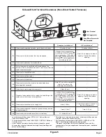
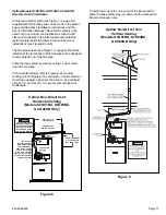
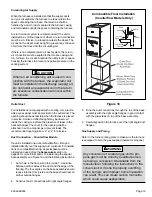
Figure 6
Upflow Direct Vent – Horizontal Venting
(Models G1D91BU, G1D93BU,
& CG90UB Only)
* The 18" dimension is the minimum
recommended height for extremely
cold areas. In these areas,
moisture in the flue gases may
condense and freeze on the air
intake if this height is reduced. In
milder climates, this may be
reduced to a minimum of 6".
Height may be increased as
needed provided total length is not
exceeded.
(CL
O
SE
D)
DRAI
N
H
O
L
E
T
H
RU.
59.
69/
56.
64
THE VENT SYSTEM OF
THE FURNACE MUST
BE SELF-SUPPORTING
AND
MUST NOT APPLY ANY
WEIGHT LOAD TO THE
COMBUSTION
BLOWER.
CAUTION
FLUE PIPE
THIS PIECE
IS OPTIONAL.
AIR INTAKE PIPE
18” *
RUN PITCH = 1/4”
PER FOOT MIN.
SEE TABLE FOR
PROPER PIPE SIZE.
HEIGHT TO PROVIDE
12” CLEARANCE TO
MAX. SNOW LEVEL.
AIR INTAKE PIPE
6”
CONDENSATE
COLLAR
DO NOT INSTALL THE
RESTRICTOR PLATES IN
ANY DIRECT VENT
APPLICATIONS.
IMPORTANT
slope upward, away from the furnace, at a minimum pitch of
1/4" per foot of run, to prevent accumulation of condensate.
Do not cement air intake into the connector on burner
box. Use high temperature RTV silicone sealant so
intake pipe can be removed if service is required.
For proper operation, the vent and air intake pipe
must be installed in the same pressure zone. There-
fore, in horizontal venting applications they must be
on the same side of the house within the parameters
shown in Figure 6.
On initial start-up of the unit, some of the water used to
prime the trap system may run down into the combustion
blower and cause noise.
Upflow Models G1D91BU, G1D93BU, & CG90UB
Direct Vent Installation
An inlet air restrictor plate (see Figure 1 on page 5) is supplied
with this furnace and can be found in the plastic bag containing
these Installation Instructions and the User
’
s Information
Manual.
This restrictor plate is to be used only in non-direct
vent applications.
See the non-direct venting sections on
pages 11 and 13 for more information on installing the restrictor
plate in non-direct vent applications.
The flue pipe screen (see Figure 1 on page 5) should be
installed at the termination of the flue pipe and is designed
to keep objects out of the flue pipe. An additional screen
should
not
be placed in the intake termination. If a screen
is installed, the air intake may freeze shut.
Prime the trap system by slowly pouring 1 cup of water
down the vent pipe.
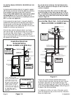
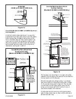
For horizontal venting, refer to Figure 6. For vertical venting,
refer to Figure 7. The vent pipe on horizontal runs must
THIS PIECE
IS OPTIONAL.
INTAKE PIPE
FLUE PIPE
3” MIN. - 48” MAX.
Overhead View
Upflow Direct Vent – Vertical Venting
(Models G1D91BU, G1D93BU,
& CG90UB Only)
Figure 7


