# 45466K003
Page 15
Outlet Duct
For installations not equipped with a cooling coil, a remov-
able access panel must be provided in the outlet duct. The
opening should be accessible when the furnace is placed
in service. Smoke or reflected light may be observed
inside the casing to indicate the presence of leaks in the
heat exchanger. The cover for the opening shall be
attached in such a manner as to prevent leaks. The
recommended opening size is 6" x 14" for all sizes.
Duct Connection – Counterflow Models
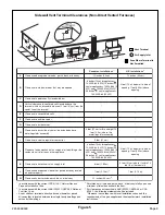
If a unit is installed on a noncombustible floor, it may be
installed directly over the supply duct or plenum. For installa-
tions on combustible flooring, a special base must be
ordered and used. (See the
Accessories
section on
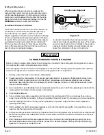
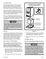
page 24 for more information.) To install using the special
base assembly, see Figure 16 and the following instructions:
1. Cut a hole in the floor, sized to provide 1" clearance
between all four sides of the duct and the edge of the
flooring. The four angles on the base assembly should
recess into the floor joists and the base should rest on
all four outside flanges.
2. Construct duct connections with right angle flanges.
Circulating Air Supply
When the furnace is installed so that the supply ducts
carry air circulated by the furnace to areas outside the
space containing the furnace, the return air shall be
handled by a duct or ducts sealed to the furnace casing
and terminated outside the space containing the furnace.
A return air duct system is recommended. If the unit is
installed in a confined space or closet, a return connection
must be run, full size, to a location outside the closet. The
air duct in the closet must be tight to prevent any entrance
of air from the closet into the circulating air.
If there is no complete return air duct system, the return
air connection must be sealed to the furnace casing and
run, full size, to a location outside the utility room or space
housing the furnace to prevent a negative pressure on the
venting system.
3. Drop the duct connections through the top of the base
assembly with the right angle flanges in good contact
with the glass tape on top of the base assembly.
4. Carefully position the furnace over the right angle duct
flanges.
Gas Supply and Piping
Refer to the furnace rating plate to make sure the furnace
is equipped to burn the gas supplied (natural or propane).
When an air conditioning unit is used in con-
junction with the furnace, the evaporator coil
must be installed in the discharge (supply) air.
Do not install an evaporator coil in the return
air; excessive condensation will occur within
the furnace.
CAUTION
Any conversion of a natural gas unit to pro-
pane gas must be done by qualified person-
nel using a conversion kit available from the
manufacturer, following the instructions in the
conversion kit. If done improperly, overfiring
of the burners and improper burner operation
can result. This can create carbon monoxide
which could cause asphyxiation.
WARNING
Combustible Floor Installation
(Counterflow Models Only)
Figure 16
1
"
Combustible
Flooring
Woven
Glass Tape
Base
Assembly
Duct
Furnace


