


# 45466K003
Page 14
Existing Venting Systems
When an existing furnace is removed or replaced, the
original venting system may no longer be sized to properly
vent the attached appliances. An improperly sized venting
system can result in spillage of flue products into the living
space, the formation of condensate, leakage, etc. See the
WARNING
box below for proper test procedure.
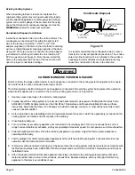
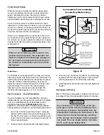
Condensate Disposal Installation
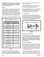
Install the condensate drain line to the unit as follows. The
condensate can be drained from either the right or left
side of the furnace. Install the 1/2" NPT x 3/4" PVC
adapter (supplied) in the drain on the side that the draining
will occur. Install the plastic pipe plug opposite of the drain.
Using 3/4" PVC pipe, make a connection from the adapter
just installed to extend just outside the unit. Install a 3/4"
PVC tee as shown in Figure 15. From the tee, install the
drain to the disposal area. The top of the tee must be left
open for proper condensate drainage.
It is recommended that the condensate drain be routed
directly to a locally acceptable disposal area. The conden-
sate drain line should not be run directly to the outdoors
especially in colder climates where temperatures may
cause the condensate to freeze in the drain line.
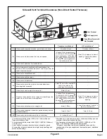
Failure to follow the steps outlined below for each appliance connected to the venting system being placed into opera-
tion could result in carbon monoxide poisoning or death.
The following steps shall be followed for each appliance connected to the venting system being placed into operation,
while all other appliances connected to the common venting system are not in operation:
1. Seal any unused openings in the common venting system.
2. Visually inspect the venting system for proper size and horizontal pitch, as required in the National Fuel Gas Code,
ANSI Z223.1/NFPA 54 (latest edition) or the CSA B149.1 Natural Gas and Propane Installation Codes and these
instructions. Determine that there is no blockage or restriction, leakage, corrosion, or other deficiencies which could
cause an unsafe condition.
3. As far as practical, close all building doors and windows between the space in which the appliance(s) connected to the
venting system are located and other spaces in the building.
4. Close fireplace dampers.
5. Turn on clothes dryers and any appliance not connected to the venting system. Turn on any exhaust fans, such as
range hoods and bathroom exhausts, so they are operating at maximum speed. Do not operate a summer exhaust fan.
6. Follow the lighting instructions. Place the unit being inspected in operation. Adjust the thermostat so appliance is
operating continuously.
7. Test for spillage from draft hood equipped appliances at the draft hood relief opening after 5 minutes of main burner
operation. Use the flame of a match or candle.
8. If improper venting is observed during any of the above tests, the venting system must be corrected in accordance with
the National Fuel Gas Code, ANSI Z223.1/NFPA 54 (latest edition) and/or the CSA B149.1 Natural Gas and Propane
Installation Codes.
9. After it has been determined that each appliance remaining connected to the venting system properly vents when
tested as outlined above, return doors, windows, exhaust fans, fireplace dampers, and any other gas-fired burning
appliance to their previous conditions of use.
CARBON MONOXIDE POISONING HAZARD
WARNING
Figure 15
Condensate Disposal
TH
R
U
.
59.69/56.64
1/2” NPT PLUG
(SUPPLIED)
1/2” NPT x 3/4” PVC ADAPTER
(SUPPLIED)
3/4” PVC
TEE MUST REMAIN
OPEN


