


# 45466K003
Page 13
Counterflow Models G1D93BC & CG90CB Non-Direct
Vent Installation
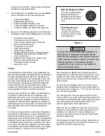
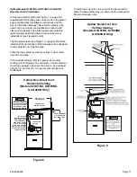
An inlet air restrictor plate (see Figure 1 on page 5) is
supplied with this furnace and can be found in the plastic
bag containing these Installation Instructions and the
User
’
s Information Manual. This restrictor plate is to be
used only in non-direct vent applications. Attach a 90
°
elbow (not supplied) to the inlet coupler and install the
restrictor plate inside the elbow in all non-direct vent
installations (see Figures 13 and 14).
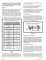
BURNER BOX
22.5° ELBOWS
STRAIGHT
INLET PIPE
G1D93BC
45,000 & 67,000 BTU/HR Units
Figure 12
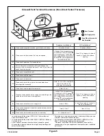
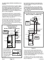
Figure 14
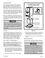
Counterflow Non-Direct Vent
Vertical Venting
(Models G1D93BC & CG90CB Only)
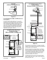
The flue pipe screen (see Figure 1 on page 5) should be
installed at the termination of the flue pipe and is designed
to keep objects out of the flue pipe.
Prime the trap system by slowly pouring 1 cup of water
down the vent pipe. For horizontal venting, refer to Figure
13. For vertical venting, refer to Figure 14. The vent pipe
on horizontal runs must slope upward, away from the
furnace, at a minimum pitch of 1/4" per foot of run, to
prevent accumulation of condensate.
On initial start-up of the unit, some of the water used to
prime the trap system may run down into the combustion
blower and cause noise.
Figure 13
Counterflow Non-Direct Vent
Horizontal Venting
(Models G1D93BC & CG90CB Only)
(CL
O
SE
D)
DRA
N
H
O
L
E
THRU.
59.69/
56.64
THE VENT SYSTEM OF
THE FURNACE MUST BE
SELF-SUPPORTING AND
MUST NOT APPLY ANY
WEIGHT LOAD TO THE
COMBUSTION BLOWER.
CAUTION
RUN PITCH = 1/4
PER FOOT MIN.
"
SEE TABLE FOR
PROPER PIPE SIZE.
6
"
HEIGHT TO PROVIDE
12 CLEARANCE TO
MAX. SNOW LEVEL.
"
GROMMET
PVC COLLAR
VENT PIPE
CONDENSATE
COLLAR
COUPLER
INLET
THE INLET AIR
RESTRICTOR PLATE
MUST BE INSTALLED
ON ALL NON-DIRECT
VENT INSTALLATIONS.
ATTACH A 90° ELBOW
TO THE INLET COUPLER
AND INSTALL THE INLET
AIR RESTRICTOR PLATE
INSIDE THE ELBOW.


