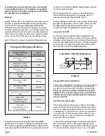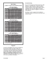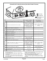
# 45466K003
Page 5
Canada, see CSA B149.1, Natural Gas and Propane
Installation Codes (latest edition).
4. The following types of installation may require
outdoor
air
for combustion, due to chemical exposures:
•
Commercial buildings
•
Buildings with indoor pools
•
Furnaces installed in laundry rooms
•
Furnaces installed in hobby or craft rooms
•
Furnaces installed near chemical storage areas
5. Exposure to the following substances in the combustion
air supply may also require
outdoor air
for combustion:
•
Permanent wave solutions
•
Chlorinated waxes and cleaners
•
Chlorine-based swimming pool chemicals
•
Water softening chemicals
•
Deicing salts or chemicals
•
Carbon tetrachloride
•
Halogen-type refrigerants
•
Cleaning solvents (such as perchloroethylene)
•
Printing inks, paint removers, varnishes, etc.
•
Cements and glues
•
Antistatic fabric softeners for clothes dryers
•
Masonry acid washing materials
•
Chlorinated laundry products
•
Hydrochloric acid
Venting
The high efficiency of this furnace is accomplished by the
removal of both sensible and latent heat from the flue gases.
The removal of latent heat results in the condensation of
moisture in the flue gases. This condensation occurs in the
secondary heat exchanger and in the vent system. There-
fore, this furnace requires special venting considerations
and the instructions must be followed to insure proper
operation. All venting must be in accordance with the codes
having jurisdiction in the area and these instructions.
Upflow models G1D91BU, G1D93BU, and CG90UB and
counterflow models G1D93BC and CG90CB can be
installed as either direct vent or non-direct vent units. A
direct vent (two pipe) installation requires that all the air
necessary for combustion be supplied from outside the
dwelling through an air intake pipe. A non-direct vent (one
pipe) installation uses air from inside the dwelling for
combustion.
The furnace is shipped with the air inlet pipe terminated to
the top panel for either inside or outside combustion air. An
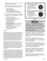
inlet air restrictor plate (see Figure 1) is supplied with this
furnace and can be found in the plastic bag containing these
Installation Instructions and the User
’
s Information Manual.
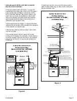
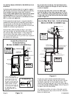
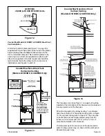
For installations using inside air for combustion (non-direct
vent), attach a 90
°
elbow (not supplied) to the inlet coupler
and install the restrictor plate inside the elbow (see Figures
8 and 9 on page 11 or Figures 13 and 14 on page 13).
If at any time in the future the installation of
this furnace is changed to require outside
fresh air for combustion, the inlet air restrictor
plate must be removed. Failure to remove the
inlet air restrictor could cause improper
operation that can result in a fire hazard or
carbon monoxide injury.
WARNING
Also included in the plastic bag containing the inlet air
restriction plate is a flue pipe screen (see Figure 1). In all
installations, this screen should be installed at the termi-
nation of the flue pipe and is designed to keep objects out
of the flue pipe.
For either type of installation (direct or non-direct vent),
special venting considerations must be followed. Refer to
the proper section in pages 10
–
13 for the type of furnace
and venting being installed.
The venting system must be supported with mounting
straps to prevent any weight load from being applied to the
vent blower. Horizontal vent pipe must be supported every
5' and vertical pipe should be supported every 10' to
prevent sagging and provide rigid support.
When a furnace is installed as direct vent, provisions for
ventilation air should follow the same requirements as if
installed as non-direct vent. Proper ventilation air is
necessary to maintain furnace component temperatures
within acceptable limits.
All vents passing through floors, ceilings, and walls must
be installed in accordance with National Fuel Gas Code,
ANSI Z223.1/NFPA 54 (latest edition).
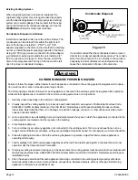
Inlet Air Restrictor Plate
Flue Pipe Screen
The inlet air restrictor plate
must
be installed in all
installations using inside air
for combustion (non-direct
vent).
The flue pipe screen
should be installed at the
termination of the flue pipe
in all installations.
Figure 1


