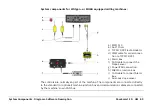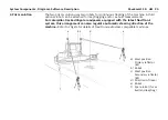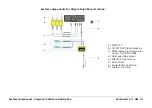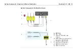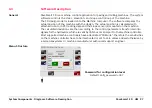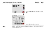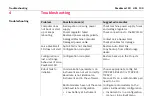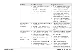
System Components, Diagrams, Software Description
PaveSmart 3D UM
95
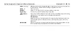
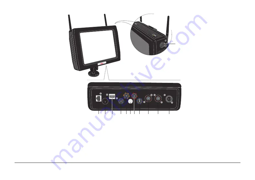
a) Ethernet connector
b) Ventilation cap
c) USB A Host connector
d) COM 1 serial port
e) Keyboard connector
f) 2A fuse for outgoing
power
g) USB B Device connector
h) COM 2 serial port
i) COM 3 serial/CAN 1 port
j) COM 4 serial/CAN 2 port
k) Power connector
l) Power key
USB
USB connection supports Leica Geosystems USB storage device or
standard USB keyboards supported by Windows XP Embedded only.
Never remove the USB storage device until file read/write/copy opera-
tions are completed, as this may cause file loss or corruption.
Do not attach
any USB device which needs additional driver installation,
as this may cause configuration corruption or installation problems.
Wi
Fi
LAN
USB A
COM 1
COM 2
COM 3/CAN 1 COM 4/CAN 2
POWER
FUSE 2A
KEYBOARD USB B
a
b
c
d e f g h
i
j
k
l
Содержание MCR-900
Страница 1: ...Leica PaveSmart 3D User Manual Version 5 0 English ...
Страница 11: ...How to use this Manual PaveSmart 3D UM 11 ...
Страница 21: ...Getting Started PaveSmart 3D UM 21 Work Screen for Milling Machines a b d c e f g h i ...
Страница 27: ...Getting Started PaveSmart 3D UM 27 Work Screen Mainline Concrete Paver a b c d f g h i j e ...
Страница 30: ...PaveSmart 3D UM 30 Getting Started Work Screen Trimmer a b d c e f g h i j ...
Страница 99: ...System Components Diagrams Software Description PaveSmart 3D UM 99 ...
Страница 107: ...Troubleshooting PaveSmart 3D UM 107 ...
Страница 136: ...PaveSmart 3D UM 136 Technical Data Mounting RAM mounting Parameter Data ...
Страница 137: ...Technical Data PaveSmart 3D UM 137 ...

