78
System Components, Diagrams, Software Description
3
System Components, Diagrams, Software Description
3.1
Hardware Descriptions
General information
Even though the hardware components are designed for construction site conditions, the
components have to be treated and transported in a careful manner. Therefore we strongly
recommend use of the supplied packaging for transport and study the relevant documenta-
tion for cleaning and maintenance work (refer to "5 Care and Transport").
System hardware
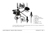
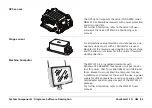
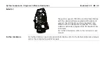
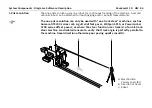
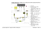
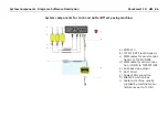
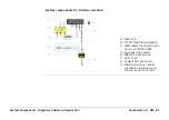
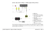
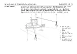
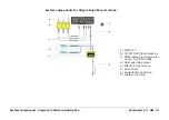
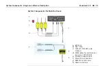
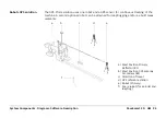
The installed components on the machine comprise a Machine Computer with attached radio
modem(s) to communicate with the robot(s), dual slope sensor, mast(s) with attached
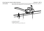
reflector or optional GPS antenna. As well as the installed components on the machine,
Robot(s) with radio modem(s) need to be set up. In case of the GPS option without an avail-
able correction signal, a reference station setup is additionally required.
Содержание MCR-900
Страница 1: ...Leica PaveSmart 3D User Manual Version 5 0 English ...
Страница 11: ...How to use this Manual PaveSmart 3D UM 11 ...
Страница 21: ...Getting Started PaveSmart 3D UM 21 Work Screen for Milling Machines a b d c e f g h i ...
Страница 27: ...Getting Started PaveSmart 3D UM 27 Work Screen Mainline Concrete Paver a b c d f g h i j e ...
Страница 30: ...PaveSmart 3D UM 30 Getting Started Work Screen Trimmer a b d c e f g h i j ...
Страница 99: ...System Components Diagrams Software Description PaveSmart 3D UM 99 ...
Страница 107: ...Troubleshooting PaveSmart 3D UM 107 ...
Страница 136: ...PaveSmart 3D UM 136 Technical Data Mounting RAM mounting Parameter Data ...
Страница 137: ...Technical Data PaveSmart 3D UM 137 ...

