


7. 3D ASSIST DISPLAY FEATURE
71
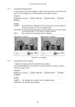
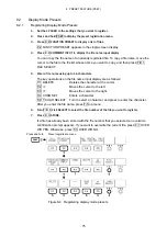
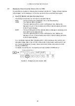
5. Set F•2 CURSOR SELECT to L/R.
6. Turn F•D 1 LEFT POS to match the L cursor with the video signal for the left eye.
Press F•D 1 to move the cursor to approximately the center of the screen.
7. Turn F•D 1 RIGHT POS to match the R cursor with the video signal for the right eye.
The measured disparity is displayed at the bottom of the screen.
Press F•D 2 to move the cursor to approximately the center of the screen.
●
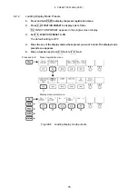
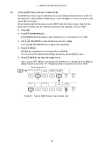
To Move the V Cursor
It is useful to use the V cursor when you match the positions of the L and R cursors.
Also, the luminance levels at the cursor intersections are displayed.
To move the V cursor, set F•2 CURSOR SELECT to V/TRACK, and then turn F•D 1
VERT POS. Press F•D 1 to move the cursor to the center of the screen.
●
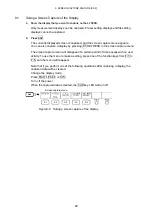
To Move the L and R Cursors at the Same Time
To move the L and R cursors at the same time, set F•2 CURSOR SELECT to
V/TRACK, and then turn F•D 2 LR TRACK POS.