


2. SPECIFICATIONS
9
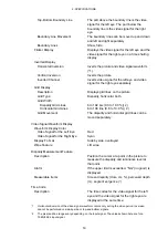
2.3.8
Video Signal Waveform Display
Waveform Operations
Display Modes
Overlay Display
Overlays component signals.
Parade Display
Displays component signals side by side.
Blanking Period
H and V blanking periods can be masked.
RGB Conversion
Converts a YC
B
C
R
signal into an RGB signal
and displays the result.
Pseudo-Composite Display
Artificially converts component signals into
composite signals and displays the result.
Channel Assignment
In RGB conversion display, the order can be set
to GBR order or RGB order.
Line Select
Displays the selected line.
Sweep Modes
H and V
Contrast
LOW, MIDDLE, HIGH, or MONOTONE
Vertical Axis
Gain
×1 or ×5
Variable Gain
×0.2 to ×2.0
Amplitude Accuracy
≤
±0.5 %
HD Frequency Response
Y Signal
≤
±0.5 % for 1 to 30 MHz
C
B
C
R
Signal
≤
±0.5 % for 0.5 to 15 MHz
Low-Pass Attenuation
≥
20 dB (at 20 MHz)
SD Frequency Response
Y Signal
≤
±0.5 % for 1 to 5.75 MHz
C
B
C
R
Signal
≤
±0.5 for 0.5 to 2.75 MHz
Low-Pass Attenuation
≥
20 dB (at 3.8 MHz)
Horizontal Axis
Line Display
×1, ×10, ×20, ACTIVE, or BLANK
Field Display
×1, ×20, or ×40
Cursor Measurement
Types
Horizontal Cursors
2 (REF and DELTA)
Vertical Cursors
2 (REF and DELTA)
Amplitude Measurement
%, mV, or R%
Time Measurement
sec
Frequency Display
Computes and displays the frequency with the
length of one period set to the time between
two cursors.
Scale
Type
V, %, 150%, 1023, or 3FF
Color Choices
7
Thumbnail Display
Can display thumbnails of picture displays and
audio level meters.
Horizontal Marker Display
Type
mV or %
Number of Markers
1 or 2