


5. SYSTEM SETTINGS (SYS)
41
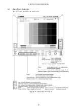
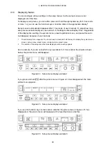
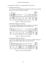
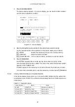
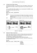
5.4
Configuring the Display
To set the timecode, error counter, input, and input SDI signal display formats, access F•4
INFORMATION in the system menu.
SYS
→
F•2 DISPLAY
→
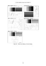
Figure5-6 INFORMATION menu
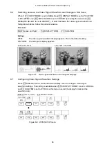
5.4.1
Selecting the Timecode Display Format
To select the display format for the SDI input signal timecode, follow the procedure below.
The timecode must conform to SMPTE 12M-2. Also, when the link format is set to dual,
only the timecode embedded in link A is displayed.
The display format you select here also applies to the event log of the status display.
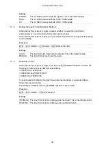
Procedure
SYS
→
F•2 DISPLAY
→
F•4 INFORMATION
→
F•1 TIME CODE
Settings
LTC:
The SDI input signal LTC timecode is displayed in the upper right of the
screen.
This is the default setting.
VITC:
The SDI input signal VITC timecode is displayed in the upper right of the
screen.
OFF:
No timecodes are displayed.
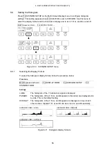
5.4.2
Displaying the Error Counter and Time
To select whether to show or hide the error counter (VIDEO_ERR, AUDIO_ERR, and
GAMUT_ERR) and time (TIME and LAPSED) in the upper left of the screen, follow the
procedure below.
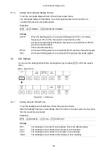
Procedure
SYS
→
F•2 DISPLAY
→
F•4 INFORMATION
→
F•2 ERROR COUNTER
Settings
ON:
The error counter and the time are displayed. This is the default setting.
OFF:
The error counter and the time are not displayed.