


6. MULTI-SCREEN DISPLAY FEATURE (MULTI)
53
6.4
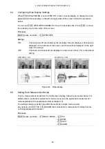
Configuring Wipe Display Settings
When F•2 DISPLAY MODE is set to WFM+PIC in the 2-channel display, to display the video
signal waveforms separately on the left and right sides of the screen, follow the procedure
below.
You can use F•D 1 WFM WIPE VARIABLE to move the boundary line. Press F•D 1 to move
the boundary line to the center of the screen.
Procedure
MULTI (press and hold)
→
F•4 WFM WIPE
Settings
ON:
Channels A and B are divided by the boundary line and displayed. Channel A is
displayed on the left side of the screen, and channel B is displayed on the right
side of the screen.
OFF:
Channel A and channel B are displayed on top of each other. This is the default
setting.
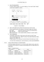
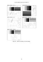
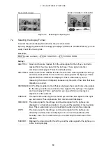
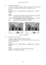
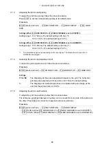
WFM WIPE = ON
WFM WIPE = OFF
Figure 6-6 Wipe display
6.5
Setting Each Measurement Mode
To set a measurement mode from the multi-screen display, follow the procedure below. For
details about a particular measurement mode's menu, see the appropriate measurement
mode explanation (the explanations start at chapter 10).
The settings that you specify here affect the settings in single mode as well.
Any options out of F•1 PIC to F•4 AUDIO that correspond to measurement modes that are
not being displayed are hidden.
Procedure
MULTI (press and hold)
→
F•3 MULTI MENU
→
F•1 PIC
→
F•2 WFM
→
F•3 VECT
→
F•4 AUDIO