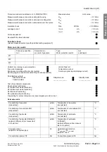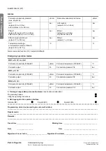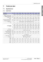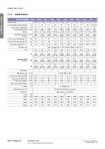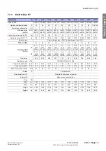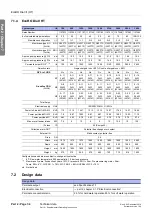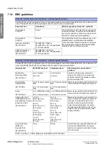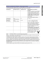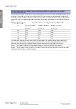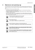
Technical data
Part 2 • Page 7-7
Part 2 – Supplementary Operating Instructions
Rev. 4.00 December 2014
Software version 1.04
EcoRO Dia I/II (HT)
Part 2 • Chapt
er 7
7.8
Membrane pressure pipe
7.9
Circuit diagram
7.10 Control
7.11
Command equipment
The control system consists of an operating unit (with CPU) and a power pack. The power element can be
supplemented by an external data and address bus. The operating unit and the power pack are connected
by means of a flat ribbon cable. With the exception of RS232, external connections are made with plug
block terminals via the power pack.
7.11.1 LCD display
7.11.2 LED display
NOTICE
Keep pressure at UV1 stabil at all times!
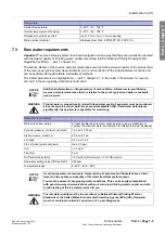
Membrane pressure pipe MM 8040
Pressure
max. 25 bar / 362.6 psi
Material
1.4404
Connections
Intake pump
Permeate drain
Concentrate drain
Weld-on tapered connector NW 25 top R ¼"
Weld-on tapered connector NW 15 top
Weld-on tapered connector NW 25 on the side
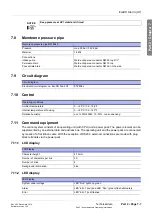
Circuit diagram
Electrical circuit diagram no. EcoRO Dia II HT
87243xx
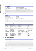
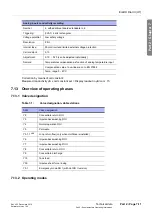
Operating conditions
Ambient temperature
0…+40°C / 32…104°F
Internal temperature of housing
0…+60°C / 32…140°F
Relative humidity:
acc. to DIN 40040, 15–75%, non-condensing
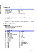
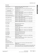
LCD display
Character height
4.75 mm
Number of characters per line
20
Number of lines
4
Background illumination:
blue
LED display
System under voltage
LED “Run” lights up green
Alarm
LED “Error” (red) and LED “Run” (green) flash alternately
Error
LED “Error” (red) flashes

