Rev. 4.00 December 2014
Software version 1.04
Part 2 • Page 7-4
Technical data
Part 2 – Supplementary Operating Instructions
EcoRO Dia I/II (HT)
Part 2 • Chapter 7
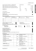
7.1.4
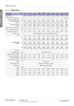
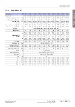
EcoRO Dia II HT
Configurations and data are subject to change without notice
*
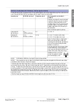
6°C Raw water temperature, 500 ppm salinity, 3,5 bar loop pressure
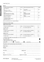
*** Membrane 3 years, flux decline 3 years: 10%; Pr pressure RO II = 2bar; Pre pressure ring main = 2bar;
Temp. RW = 6°C; WCF RO 1 = 78%; WCF RO 2 = 85% OVERALL WCF = 75%
n.d. Not defined
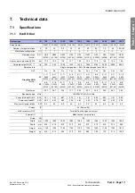
7.2
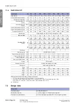
Design data
System type
l/h
700
900
1050
1400
1800
2100
2450
2800
3600
Sales Number
1107072 1107093 1107107 1107142 1107183 1107213 1107248 1107282 1107362
# of calculated dialysis stations
#
20
25
30
40
50
60
70
80
100–120
Membrane configuration
I / II
1+1
1+1
1+1
2+2
2+2
2+2
3+2
3+3
4+4
Membrane-type RO
(Art.No)
RO I G20FTS
(49773)
G20FTS
(49773)
G20FTS
(49773)
G20FTS
(49773)
G20FTS
(49773)
G20FTS
(49773)
G20FTS
(49773)
G20FTS
(49773)
G20FTS
(49773)
Membrane-type RO
(Art.No)
RO II G20TS
(49772)
G20FTS
(49773)
G20FTS
(49773)
G20TS
(49772)
G20FTS
(49773)
G20FTS
(49773)
G20FTS
(49773)
G20TS
(49772)
G20FTS
(49773)
Approx. pump pressure @ PI 2
bar
17.3
19.2
19.0
16.5
19.2
21.0
18.1
19.6
19.3
Approx. pump pressure @ PI 4
bar
14.8
16.1
18.2
14.0
15.1
16.4
19.2
16.5
14.0
Permeate output RO II*, ***
l/h
700
900
1050
1400
1800
2100
2500
2800
3600
Rejection rate
Single charged Ions > 95%, Double charged Ions > 98 %
ÜV2: ref. HRS
No
No
No
No
No
No
No
No
No
M1
5–11
3kW
(52183)
5–11
3kW
(52183)
5–15
4kW
(52185)
5–11
3kW
(52183)
5–11
3kW
(52183)
5–15
4kW
(52185)
5–15
4kW
(52185)
5–15
4kW
(52185)
5–15
4kW
(52185)
Grundfos CRN
(Art.No)
M2
5–8
2,2kW
(52182)
5–11
3kW
(52183)
5–11
3kW
(52183)
5–11
3kW
(52183)
5–11
3kW
(52183)
5–11
3kW
(52183)
5–11
3kW
(52183)
5–11
3kW
(52183)
5–15
4kW
(52185)
M3
3–17
2,2 kW
(52180)
3–23
3kW
(52181)
3–23
3kW
(52181)
3–23
3kW
(52181)
3–23
3kW
(52181)
3–23
3kW
(52181)
5–22
5,5kW
(52163)
3–23
3kW
(52181)
5–22
5,5kW
(52163)
Total Amps
Electrical supply
V/Hz
120/208V 3P4W+G / 60Hz
Power full -load M1+M2+M3
KVA
11.0
13.12
14.27
13.12
13.12
14.27
17.44
14.27
18.59
Power part-load M1+M2
KVA
7.8
8.87
10.03
8.87
8.87
10.03
10.03
10.03
11.18
Power part-load M1
KVA
4.63
4.63
5.78
4.63
4.63
5.78
5.78
5.78
5.78
Max. overall power intake
KW
7.4
9
10
9
9
10
12.5
10
13.5
IP class
IP
54 (Pumps 55)
Collective alarm OUT
Potential free change over contact
External IN
Make contact, potential free
Drain
DN
25
Width
mm
1570
1570
1570
1890
1890
1890
1890
1905
2665
Depth
mm
950
950
950
950
950
950
950
1080
960
Height
mm
1800
1800
1800
1800
1800
1800
1800
1800
1800
Weight
kg
515
515 540
575
685
700
775
915
1050
Design data
Permeate output
see Specifications 7.1
Electrical connection
part 2, chapter 3.1.3 “Electrical connection”
Permeate concentrate ratio
25 % for hard water operation 50 % for soft water operation

