Description of components
Part 1 • Page 7-1
Part 1 – Operating Instructions
Rev. 4.00 December 2014
Software version 1.04
EcoRO Dia I/II (HT)
Part 1 • Chapt
er 7
7.
Description of components
7.1
Pipeline / Switch cabinet
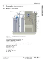
Figure 7-1:
Aquaboss
®
EcoRO Dia II HT front view
1. Main switch
2. Operating mode selection switch (position 1,0,2)
3. Display – 4 lines with 20 characters each
4. Display-guided key control
5. Butterfly valve
K1
emergency mode, via 2nd stage, normal setting closed
6. Butterfly valve
K3
emergency mode, via 1st stage, normal setting closed
7. Conductivity display (backlit)
8. “Dialysis mode” lamp
9. “Standby mode” lamp
10. “Rinsing” lamp
11. “Emergency mode” lamp
12. “fault” lamp
4
7
9
10
2
8
11
1
5
6
3
12


