
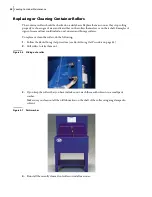


Loading Container Maintenance
59
4 h.
Remove the safety pins.
4 i.
Start the truck’s engine.
4 j.
Engage the hydraulic pump.
4 k.
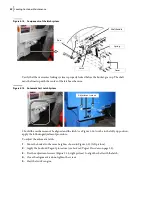
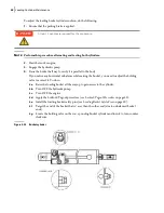
Lower the bucket and do a test by lifting it up.
Use the body guide as reference (see Figure 5
11).
N
OTE
:
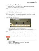
The tolerance for the horizontal alignment is ½”.
4 l.
If the adjustment of the holding valve is overdone, turn its adjustment screw ¼-turn
clockwise and test again.
5.
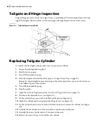
Raise the loading bucket to assess the amount of cushion needed at the upper end.
6.
Lower the loading bucket to assess the amount of cushion needed at the lower end.
7.
Lift the loading bucket all the way up to gain access to the cylinder.
8.
Turn OFF the hydraulic pump.
9.
Turn OFF the engine.
10.
Apply the Lockout/Tagout procedure (see
11.
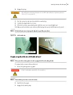
With the bucket fully raised, install the safety pins (see
12.
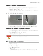
If adjustment is needed on the upper end:
12 a.
Locate the adjustment screw on the cylinder near the head.
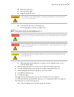
Do not forget to fully open the hydraulic shut-off valve before starting the engine (see
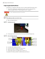
Always turn OFF the engine and the hydraulic system when performing tasks on the roof.
Always install the bucket safety pins when the bucket is raised and adjustments are being
done on the cylinders.
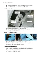
Do not forget to remove the bucket safety pins when you need to test the cylinders by
moving the bucket.
WARNING!
DANGER!
DANGER!
CAUTION!
Содержание Top Select
Страница 1: ...TOP SELECT TM MAINTENANCE MANUAL...
Страница 2: ......
Страница 3: ...TOP SELECT MAINTENANCE MANUAL...
Страница 8: ...vi Table of Contents...
Страница 34: ...26 Safety...
Страница 40: ...32 General Cleanliness...
Страница 72: ...64 Loading Container Maintenance...
Страница 104: ...96 Preventive Maintenance...
Страница 121: ...Lubrication 113 Figure 11 2 Body hinges Grease Fittings on Body Figure 11 3 Tailgate and hooks...
Страница 122: ...114 Lubrication Figure 11 4 Partition Figure 11 5 Optional Maximizer Location of lube zerks...
Страница 123: ...Lubrication 115 Figure 11 6 Roof hinges and loading cylinders...
Страница 124: ...116 Lubrication Figure 11 7 Lube chart...
Страница 132: ...124 Troubleshooting...
Страница 134: ...126 Hydraulic and Pneumatic Circuit Diagrams Hydraulic Schematics Single Side Bucket...
Страница 135: ...Hydraulic and Pneumatic Circuit Diagrams 127 Single Side Bucket w Maximizer...
Страница 136: ...128 Hydraulic and Pneumatic Circuit Diagrams Dual Side Bucket...
Страница 137: ...Hydraulic and Pneumatic Circuit Diagrams 129 Dual Side Bucket w Maximizer...
Страница 138: ...130 Hydraulic and Pneumatic Circuit Diagrams Dual Side Bucket w Maximizer and Dual Tailgate Cylinder...
Страница 139: ...Hydraulic and Pneumatic Circuit Diagrams 131 Air System Schematics TS 1000 w Options...
Страница 140: ...132 Hydraulic and Pneumatic Circuit Diagrams TS 2000 w Options...


