13
Hydraulic and
Pneumatic Circuit
Diagrams
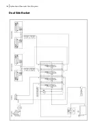
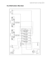
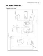
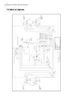
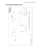
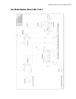
The following schematics show you the hydraulic and
pneumatic circuits and the various components that
are connected to them.
These schematics can be used to locate a particular
components and can be helpful for troubleshooting.
The first set of schematics is related to the hydraulic
system and the second set to the pneumatic (air)
system.
N
OTE
:
The following schematics vary according to the
truck configuration and the options that have been
chosen.
Содержание Top Select
Страница 1: ...TOP SELECT TM MAINTENANCE MANUAL...
Страница 2: ......
Страница 3: ...TOP SELECT MAINTENANCE MANUAL...
Страница 8: ...vi Table of Contents...
Страница 34: ...26 Safety...
Страница 40: ...32 General Cleanliness...
Страница 72: ...64 Loading Container Maintenance...
Страница 104: ...96 Preventive Maintenance...
Страница 121: ...Lubrication 113 Figure 11 2 Body hinges Grease Fittings on Body Figure 11 3 Tailgate and hooks...
Страница 122: ...114 Lubrication Figure 11 4 Partition Figure 11 5 Optional Maximizer Location of lube zerks...
Страница 123: ...Lubrication 115 Figure 11 6 Roof hinges and loading cylinders...
Страница 124: ...116 Lubrication Figure 11 7 Lube chart...
Страница 132: ...124 Troubleshooting...
Страница 134: ...126 Hydraulic and Pneumatic Circuit Diagrams Hydraulic Schematics Single Side Bucket...
Страница 135: ...Hydraulic and Pneumatic Circuit Diagrams 127 Single Side Bucket w Maximizer...
Страница 136: ...128 Hydraulic and Pneumatic Circuit Diagrams Dual Side Bucket...
Страница 137: ...Hydraulic and Pneumatic Circuit Diagrams 129 Dual Side Bucket w Maximizer...
Страница 138: ...130 Hydraulic and Pneumatic Circuit Diagrams Dual Side Bucket w Maximizer and Dual Tailgate Cylinder...
Страница 139: ...Hydraulic and Pneumatic Circuit Diagrams 131 Air System Schematics TS 1000 w Options...
Страница 140: ...132 Hydraulic and Pneumatic Circuit Diagrams TS 2000 w Options...


