34
Monthly Visual Inspection
Visual Inspection of the Loading Bucket
To visually inspect the loading bucket, proceed this way:
1.
Follow the three preparation steps as described on page 33 before carrying out the visual
inspection operations.
2.
Start the truck’s engine.
3.
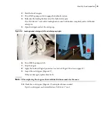
Turn ON the pump switch to engage the hydraulic system.
4.
Move the bucket up and down and look for any irregular movement or improper cushioning.
If the bucket makes irregular movements or stops abruptly at either end of its up and down
movement, any of the following parts may need to be replaced:
Figure 4
-
1 Bucket Moving Parts
• Rollers (there are 4 rollers; 2 inside each rail at each end of the bucket) - They should be rolling
smoothly. If movement is not regular, see
Replacing or Cleaning Container Rollers
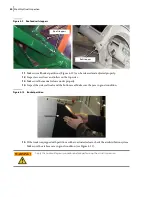
• Sliding shoe (see Figure 4
1) - This part is made out of teflon. Check if there are signs of wear on
it. Replacement must be done before it is completely worn out. See
• Rails (there are 2 rails - one at each end of the bucket) - Look for dirt or any small object that
could cause premature wear. There should be no grease in the rails, because grease can cause
glass, grit and other deposits to stick inside the rails causing premature wear of the rollers.
Remove grease using pressure steam or solvent.
• Rods between the bucket and the cylinder (2) - Check for loose linkages, locknuts or bad
threads. Check all missing anchor bolts or cotter pin. For rod maintenance and repair, see
Apply the Lockout/Tagout procedure before carrying out inspection, parts replacement
or maintenance.
Sliding shoe
Rails
WARNING!
Содержание Top Select
Страница 1: ...TOP SELECT TM MAINTENANCE MANUAL...
Страница 2: ......
Страница 3: ...TOP SELECT MAINTENANCE MANUAL...
Страница 8: ...vi Table of Contents...
Страница 34: ...26 Safety...
Страница 40: ...32 General Cleanliness...
Страница 72: ...64 Loading Container Maintenance...
Страница 104: ...96 Preventive Maintenance...
Страница 121: ...Lubrication 113 Figure 11 2 Body hinges Grease Fittings on Body Figure 11 3 Tailgate and hooks...
Страница 122: ...114 Lubrication Figure 11 4 Partition Figure 11 5 Optional Maximizer Location of lube zerks...
Страница 123: ...Lubrication 115 Figure 11 6 Roof hinges and loading cylinders...
Страница 124: ...116 Lubrication Figure 11 7 Lube chart...
Страница 132: ...124 Troubleshooting...
Страница 134: ...126 Hydraulic and Pneumatic Circuit Diagrams Hydraulic Schematics Single Side Bucket...
Страница 135: ...Hydraulic and Pneumatic Circuit Diagrams 127 Single Side Bucket w Maximizer...
Страница 136: ...128 Hydraulic and Pneumatic Circuit Diagrams Dual Side Bucket...
Страница 137: ...Hydraulic and Pneumatic Circuit Diagrams 129 Dual Side Bucket w Maximizer...
Страница 138: ...130 Hydraulic and Pneumatic Circuit Diagrams Dual Side Bucket w Maximizer and Dual Tailgate Cylinder...
Страница 139: ...Hydraulic and Pneumatic Circuit Diagrams 131 Air System Schematics TS 1000 w Options...
Страница 140: ...132 Hydraulic and Pneumatic Circuit Diagrams TS 2000 w Options...


