


106
Maximizer Maintenance
6.
Turn OFF the hydraulic pump and stop the engine.
7.
Apply the Lockout/Tagout procedure (see
8.
Disconnect all hydraulic hoses and fittings from the cylinder.
Save these for the new cylinder to be installed.
9.
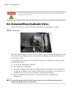
At the cylinder base, remove the bolt retaining the pin to the pillow block.
10.
Remove the pin.
11.
Attach the cylinder to a safe lifting device and slowly lift it out of the body.
Figure 10
-
10 Removing pin
Installing a New Cylinder
N
OTE
:
2 people are required to carry out this procedure.
To install a new Maximizer cylinder, proceed as follows:
1.
Make sure the Maximizer panel is positioned to the far front of the body.
2.
Use a safe lifting device to carefully slide the cylinder into position.
3.
Put back the pin at the base of the cylinder.
4.
Put back the bolt securing the pin to the pillow block.
5.
Connect the hydraulic hoses and fittings that were set aside to the newly installed cylinder.
6.
Free the cylinder from the lifting device.
7.
If needed, remove the bolts from the cylinder head cover and lift up the cover (see Figure 10
9).
8.
Start the engine and engage the hydraulic system.
9.
Have a helper move the Maximizer control handle (see Figure 10
1) to fully extend the cylinder
while you make sure the cylinder head is correctly aligned with the opening at the base of the
Maximizer panel and correct it if needed.
10.
Once the cylinder head has correctly been installed on its bracket, turn OFF the hydraulic pump
and stop the engine.
Check the shut-off valve on the suction line is completely open before engaging the
hydraulic system.
WARNING!
Содержание Top Select
Страница 1: ...TOP SELECT TM MAINTENANCE MANUAL...
Страница 2: ......
Страница 3: ...TOP SELECT MAINTENANCE MANUAL...
Страница 8: ...vi Table of Contents...
Страница 34: ...26 Safety...
Страница 40: ...32 General Cleanliness...
Страница 72: ...64 Loading Container Maintenance...
Страница 104: ...96 Preventive Maintenance...
Страница 121: ...Lubrication 113 Figure 11 2 Body hinges Grease Fittings on Body Figure 11 3 Tailgate and hooks...
Страница 122: ...114 Lubrication Figure 11 4 Partition Figure 11 5 Optional Maximizer Location of lube zerks...
Страница 123: ...Lubrication 115 Figure 11 6 Roof hinges and loading cylinders...
Страница 124: ...116 Lubrication Figure 11 7 Lube chart...
Страница 132: ...124 Troubleshooting...
Страница 134: ...126 Hydraulic and Pneumatic Circuit Diagrams Hydraulic Schematics Single Side Bucket...
Страница 135: ...Hydraulic and Pneumatic Circuit Diagrams 127 Single Side Bucket w Maximizer...
Страница 136: ...128 Hydraulic and Pneumatic Circuit Diagrams Dual Side Bucket...
Страница 137: ...Hydraulic and Pneumatic Circuit Diagrams 129 Dual Side Bucket w Maximizer...
Страница 138: ...130 Hydraulic and Pneumatic Circuit Diagrams Dual Side Bucket w Maximizer and Dual Tailgate Cylinder...
Страница 139: ...Hydraulic and Pneumatic Circuit Diagrams 131 Air System Schematics TS 1000 w Options...
Страница 140: ...132 Hydraulic and Pneumatic Circuit Diagrams TS 2000 w Options...


