52
Loading Container Maintenance
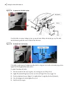
Figure 5
-
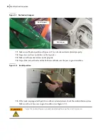
14 Components of the latch system
Verify that the overcenter locking system is properly locked before the bucket goes up. The shaft
must be lined up with the center of the latch mechanism.
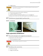
Figure 5
-
15 Automatic Cart Latch System
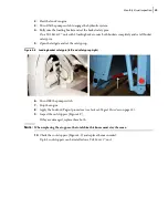
Should the mechanism not be aligned and the latch (see Figure 5
16) not be in the fully up position,
apply the following adjustment procedure.
To adjust the automatic latch:
1.
Move the bucket to the same height as shown in Figure 5
15 (left picture).
2.
Apply the Lockout/Tagout procedure (see
3.
Use the adjustment screws (Figure 5
15, right picture) to align the shaft with the latch.
4.
Once the alignment is done, tighten the screws.
5.
Start the truck’s engine.
Shaft handle
Latch
Rod
Spring
Cover
Adjustment screws
Содержание Top Select
Страница 1: ...TOP SELECT TM MAINTENANCE MANUAL...
Страница 2: ......
Страница 3: ...TOP SELECT MAINTENANCE MANUAL...
Страница 8: ...vi Table of Contents...
Страница 34: ...26 Safety...
Страница 40: ...32 General Cleanliness...
Страница 72: ...64 Loading Container Maintenance...
Страница 104: ...96 Preventive Maintenance...
Страница 121: ...Lubrication 113 Figure 11 2 Body hinges Grease Fittings on Body Figure 11 3 Tailgate and hooks...
Страница 122: ...114 Lubrication Figure 11 4 Partition Figure 11 5 Optional Maximizer Location of lube zerks...
Страница 123: ...Lubrication 115 Figure 11 6 Roof hinges and loading cylinders...
Страница 124: ...116 Lubrication Figure 11 7 Lube chart...
Страница 132: ...124 Troubleshooting...
Страница 134: ...126 Hydraulic and Pneumatic Circuit Diagrams Hydraulic Schematics Single Side Bucket...
Страница 135: ...Hydraulic and Pneumatic Circuit Diagrams 127 Single Side Bucket w Maximizer...
Страница 136: ...128 Hydraulic and Pneumatic Circuit Diagrams Dual Side Bucket...
Страница 137: ...Hydraulic and Pneumatic Circuit Diagrams 129 Dual Side Bucket w Maximizer...
Страница 138: ...130 Hydraulic and Pneumatic Circuit Diagrams Dual Side Bucket w Maximizer and Dual Tailgate Cylinder...
Страница 139: ...Hydraulic and Pneumatic Circuit Diagrams 131 Air System Schematics TS 1000 w Options...
Страница 140: ...132 Hydraulic and Pneumatic Circuit Diagrams TS 2000 w Options...


