92
Air System Maintenance
Air-Actuated Main Hydraulic Valve
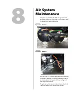
The main hydraulic valve, which controls the body functions, is activated by air actuators.
Figure 8
-
3 Air actuators
When the tailgate or body lever on the console is actuated, air pressure passing through the lever will
activate the corresponding air actuator on the main valve resulting in a movement of the hydraulic
spool inside the valve.
To avoid affecting control air systems on the vehicle (especially in cold weather conditions), apply
the following procedure:
1.
Ensure that the parking brake is applied.
2.
Drain all air tanks on a daily basis.
3.
Change the cartridge in the air dryer according to the chassis manufacturer’s recommendations.
On this type of equipment, the compressor works all the time mostly due to the frequent use of
the brake system. As a result, a lot of moisture is injected into the air system.
4.
Twice a year, lubricate the air actuators on the main control valve with light oil (low
temperature).
N
OTE
:
For vehicle equipped with an alcohol evaporator, please refer to the chassis manufacturer
dealer for proper maintenance instructions.
Apply the Lockout/Tagout procedure at all times when maintenance and inspection are
performed on the vehicle.
DANGER!
Содержание Top Select
Страница 1: ...TOP SELECT TM MAINTENANCE MANUAL...
Страница 2: ......
Страница 3: ...TOP SELECT MAINTENANCE MANUAL...
Страница 8: ...vi Table of Contents...
Страница 34: ...26 Safety...
Страница 40: ...32 General Cleanliness...
Страница 72: ...64 Loading Container Maintenance...
Страница 104: ...96 Preventive Maintenance...
Страница 121: ...Lubrication 113 Figure 11 2 Body hinges Grease Fittings on Body Figure 11 3 Tailgate and hooks...
Страница 122: ...114 Lubrication Figure 11 4 Partition Figure 11 5 Optional Maximizer Location of lube zerks...
Страница 123: ...Lubrication 115 Figure 11 6 Roof hinges and loading cylinders...
Страница 124: ...116 Lubrication Figure 11 7 Lube chart...
Страница 132: ...124 Troubleshooting...
Страница 134: ...126 Hydraulic and Pneumatic Circuit Diagrams Hydraulic Schematics Single Side Bucket...
Страница 135: ...Hydraulic and Pneumatic Circuit Diagrams 127 Single Side Bucket w Maximizer...
Страница 136: ...128 Hydraulic and Pneumatic Circuit Diagrams Dual Side Bucket...
Страница 137: ...Hydraulic and Pneumatic Circuit Diagrams 129 Dual Side Bucket w Maximizer...
Страница 138: ...130 Hydraulic and Pneumatic Circuit Diagrams Dual Side Bucket w Maximizer and Dual Tailgate Cylinder...
Страница 139: ...Hydraulic and Pneumatic Circuit Diagrams 131 Air System Schematics TS 1000 w Options...
Страница 140: ...132 Hydraulic and Pneumatic Circuit Diagrams TS 2000 w Options...


