6 | Function description
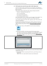
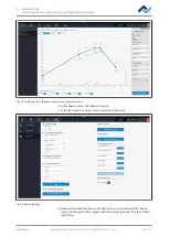
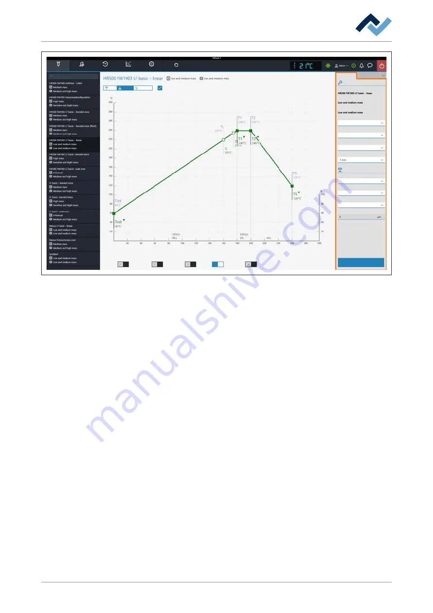
Temporarily editing the soldering profile in the [Rework] tab
Combined
Rework
Archive
User administration
Profile management
Administration
Desoldering
Name
Placement
Profile settings
Search
Heater config
Information
Board
Component
Control sensor
Adaptor (head)
Nozzle
Dip mode
Placement mode
Drop height
TC1
No automation
Placement
Heating head position
Placement
Inspection
Soldering
Inspection
Soldering
Desoldering
Synchronize
Process automation
Manual Mode
START/REFERENCE
Component filter
Common settings
Distance 50 mm
Time
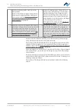
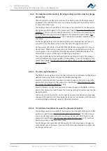
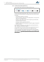
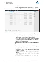
The parameters in tab [Information]
In range [
Profile settings
]:
The three bolded parameters are defined in tab [Profile management].
The following parameters can be edited here in tab [Information]:
– [Control sensor]: Selection of the temperature sensor that controls the solder-
ing process via its measured temperature. IRS [IRS] (Infrared sensor), [TC1]
(thermocouple 1) or [TC2]. The currently measured temperature of the selec-
ted sensor is displayed in field (2). The infrared sensor (IRS) is not suitable for
glossy, reflective surfaces or very small boards.
– [Adaptor (head)]: used adapter (air baffle). No function, only used to save info.
– [Heating head position]: Define the soldering distance to the PCB from 30 mm
to 70 mm.
– [Heating head position]: eating head type [L-head] (big) or [S-head] (small).
– [Lens]: Used lens. No function, only used to save info.
– [pipette]: Used pipette. No function, only used to save info.
In range [
Placement
]:
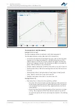
– [Dip mode]: You can choose from three soldering methods:
– [No automation]: Normal soldering without dipping any flux material and
without using a component that is coated with solder paste. The compon-
ent is picked up from the component tray, aligned and placed on the sol-
dering position.
– [Auto. Dip]: Place the dip stencil prepared with flux material on a compon-
ent tray. The component is lifted from another component tray and im-
mersed in the dip stencil’s flux material, aligned and placed in the soldering
position.
Ersa GmbH
Operating instructions HR 550 XL EN 3BA00247-01 | Rev. 1
66 / 157
Содержание HR 550 XL
Страница 2: ......
Страница 6: ......
Страница 22: ...2 Technical data PC system requirements Ersa GmbH Operating instructions HR 550 XL EN 3BA00247 01 Rev 1 22 157...
Страница 153: ...9 Spare and wear parts Spare parts Ersa GmbH Operating instructions HR 550 XL EN 3BA00247 01 Rev 1 153 157...
Страница 156: ...10 Annex EC Declaration of Conformity Ersa GmbH Operating instructions HR 550 XL EN 3BA00247 01 Rev 1 156 157...
Страница 157: ......

