4 | Transport, installation, storage, disposal
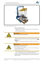
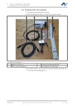
Assembling an RPC camera (optional)
5
5
5
5
6
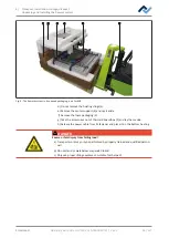
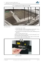
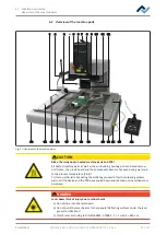
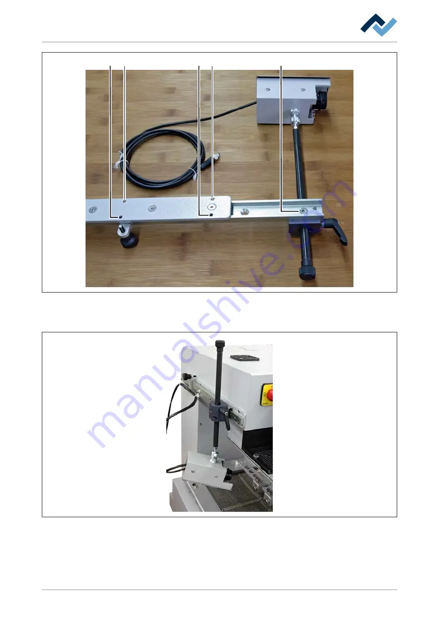
Fig. 11:
RPC camera assembled
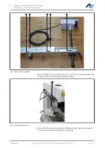
c) Mount the RPC camera with six screws (3) in the bores (5) at the left side of the
Rework System, see the following example picture.
Fig. 12:
Mounted RPC camera
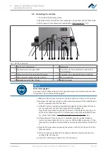
d) Connect the Ethernet cable and the LED lighting cable to the Rework System.
For this purpose, please read Chapter Connecting
Ersa GmbH
Operating instructions HR 550 XL EN 3BA00247-01 | Rev. 1
45 / 157
Содержание HR 550 XL
Страница 2: ......
Страница 6: ......
Страница 22: ...2 Technical data PC system requirements Ersa GmbH Operating instructions HR 550 XL EN 3BA00247 01 Rev 1 22 157...
Страница 153: ...9 Spare and wear parts Spare parts Ersa GmbH Operating instructions HR 550 XL EN 3BA00247 01 Rev 1 153 157...
Страница 156: ...10 Annex EC Declaration of Conformity Ersa GmbH Operating instructions HR 550 XL EN 3BA00247 01 Rev 1 156 157...
Страница 157: ......

