476671/B
281
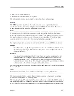
tool for debugging purposes. It is neither required nor intended for normal operation of
the MF90 system.
9
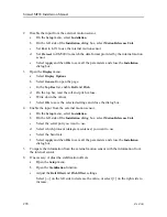
Type a custom name to identify the interface in other dialog boxes.
10
Select which datagram(s) you want to import from the sensor.
11
If relevant, specify a dedicated talker ID.
12
Provide the accurate physical location of the sensor (or its antenna) with reference to
the vessel’s coordinate system.
The position of certain sensors must be defined as an
offset
to the
Ship Origin
in the
coordinate system to maximize performance. These offset values are all required to
allow the MF90 system to give you as accurate information as possible. The degree
of accuracy offered by the MF90 system is directly related to the accuracy of the
information you enter on the
Sensor Installation
page.
a
Select the offset value on the X axis (fore-and-aft direction) from the
Ship Origin
.
Adjust with a positive value for X if the sensor is located ahead of the ship origin.
b
Select the offset value on the Y axis (athwartship) from the
Ship Origin
. Adjust
with a positive value for Y if the sensor is located on the starboard side of the
ship origin.
c
Select the offset value on the Z axis (vertical) from the
Ship Origin
. Adjust with a
positive value for Z if the sensor is located under the ship origin.
13
Select
Add
to save the new sensor interface you have defined.
The sensor interface is added to the
Installed Sensors
list on the
Sensor Installation
page.
14
At the bottom of the dialog box, select
Apply
to save your settings.
15
Repeat for each sensor interface that you need to set up.
16
Continue your work in the
Installation
dialog box, or select
OK
to close it.
Further requirements
On the left side of the
Installation
dialog box, select
Sensor Configuration
. Define the priority
of the datagrams, and set up relevant configuration parameters.
Related topics
Setting to work, page 186
Setting up the interfaces to peripheral devices, page 276
Содержание Simrad MF90
Страница 1: ...kongsberg com simrad Simrad MF90 INSTALLATION MANUAL...
Страница 2: ......
Страница 21: ...476671 B 19 Related topics Simrad MF90 page 13 Simrad MF90...
Страница 353: ...476671 B 351 Number of individual elements 480 Related topics Technical specifications page 346 Technical specifications...
Страница 369: ...476671 B 367 Drawing file...
Страница 372: ...370 476671 B Simrad MF90 Installation Manual...
Страница 373: ...476671 B 371 Related topics Installing the MF90 system hardware units page 126 Drawing file page 364 Drawing file...
Страница 375: ...476671 B 373 Drawing file...
Страница 378: ...376 476671 B Simrad MF90 Installation Manual...
Страница 379: ...476671 B 377 Related topics Installing the MF90 system hardware units page 126 Drawing file page 364 Drawing file...
Страница 384: ...382 476671 B Simrad MF90 Installation Manual...
Страница 385: ...476671 B 383 Related topics Installing the MF90 system hardware units page 126 Drawing file page 364 Drawing file...
Страница 387: ...476671 B 385 Drawing file...
Страница 388: ...386 476671 B Related topics Installing the hull unit page 99 Drawing file page 364 Simrad MF90 Installation Manual...
Страница 390: ...388 476671 B Simrad MF90 Installation Manual...
Страница 391: ...476671 B 389 Related topics Installing the hull unit page 99 Drawing file page 364 Drawing file...
Страница 393: ...476671 B 391 Drawing file...
Страница 394: ...392 476671 B Related topics Installing the hull unit page 99 Drawing file page 364 Simrad MF90 Installation Manual...
Страница 396: ...394 476671 B Related topics Installing the hull unit page 99 Drawing file page 364 Simrad MF90 Installation Manual...
Страница 398: ...396 476671 B Simrad MF90 Installation Manual...
Страница 399: ...476671 B 397 Related topics Installing the hull unit page 99 Drawing file page 364 Drawing file...
Страница 421: ......
Страница 422: ...2022 Kongsberg Maritime ISBN 978 82 8066 240 8...
Страница 423: ......
Страница 425: ......
Страница 426: ...Installation Manual Simrad MF90...

