114
476671/B
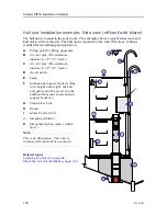
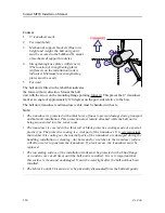
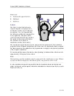
Context
1
0° transducer mark
2
Forward (label)
3
Mechanical support brackets (Due to its
height and weight, the hull unit gantry
must be secured to the bulkhead by means
of mechanical support brackets.)
4
Strengthening knee plates (stiffereners)
(The location of strengthening plates
(stiffeners) on the installation trunk is
indicated. Minimum four strengthening
plates must be used.)
5
Forward
The hull unit is fitted with a label that indicates
the forward (bow) direction. Mount the hull
unit with the arrow on the mounting flange pointing forward. This places the 0° transducer
mark at an angle of approximately 120 degrees on the port side relative to the bow.
The hull unit, transducer and transducer cable must be handled with care.
Note
• The transducer is protected with a thick layer of foam to prevent damage during transport
and hull unit installation. This protection must remain attached while the hull unit is
being manoeuvred into the sonar room.
• The transducer is covered with a thick red or black protective coating made of a special
plastic type. The protective coating is a vital part of the transducer. It is very important
that neither this coating nor the internal parts of the transducer are damaged during the
handling, installation or cleaning. Any holes and/or scratches in the transducer surface
will allow water to penetrate the transducer. If a leak occurs, the transducer must be
replaced.
• The top mating surface of the installation trunk must be protected with a blind flange
or wooden cover at all times until the hull unit is installed. It is very important that
this surface is clean and undamaged. It must be watertight after the hull unit has been
installed.
• The Motor Control Unit must never be physically dismounted from the hull unit gantry.
Simrad MF90 Installation Manual
Содержание Simrad MF90
Страница 1: ...kongsberg com simrad Simrad MF90 INSTALLATION MANUAL...
Страница 2: ......
Страница 21: ...476671 B 19 Related topics Simrad MF90 page 13 Simrad MF90...
Страница 353: ...476671 B 351 Number of individual elements 480 Related topics Technical specifications page 346 Technical specifications...
Страница 369: ...476671 B 367 Drawing file...
Страница 372: ...370 476671 B Simrad MF90 Installation Manual...
Страница 373: ...476671 B 371 Related topics Installing the MF90 system hardware units page 126 Drawing file page 364 Drawing file...
Страница 375: ...476671 B 373 Drawing file...
Страница 378: ...376 476671 B Simrad MF90 Installation Manual...
Страница 379: ...476671 B 377 Related topics Installing the MF90 system hardware units page 126 Drawing file page 364 Drawing file...
Страница 384: ...382 476671 B Simrad MF90 Installation Manual...
Страница 385: ...476671 B 383 Related topics Installing the MF90 system hardware units page 126 Drawing file page 364 Drawing file...
Страница 387: ...476671 B 385 Drawing file...
Страница 388: ...386 476671 B Related topics Installing the hull unit page 99 Drawing file page 364 Simrad MF90 Installation Manual...
Страница 390: ...388 476671 B Simrad MF90 Installation Manual...
Страница 391: ...476671 B 389 Related topics Installing the hull unit page 99 Drawing file page 364 Drawing file...
Страница 393: ...476671 B 391 Drawing file...
Страница 394: ...392 476671 B Related topics Installing the hull unit page 99 Drawing file page 364 Simrad MF90 Installation Manual...
Страница 396: ...394 476671 B Related topics Installing the hull unit page 99 Drawing file page 364 Simrad MF90 Installation Manual...
Страница 398: ...396 476671 B Simrad MF90 Installation Manual...
Страница 399: ...476671 B 397 Related topics Installing the hull unit page 99 Drawing file page 364 Drawing file...
Страница 421: ......
Страница 422: ...2022 Kongsberg Maritime ISBN 978 82 8066 240 8...
Страница 423: ......
Страница 425: ......
Страница 426: ...Installation Manual Simrad MF90...

