D
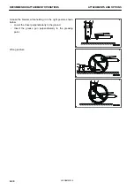
Piping on left side of arm (shaft end)
FASTER NV 12 GAS M
Connect the hydraulic circuit according the following procedures when installing the attachment.
1.
Release the pressure in hydraulic circuit. For detail see MAINTENANCE “METHOD FOR RELEASING
PRESSURE IN HYDRAULIC CIRCUIT”.
2.
Rotate the levers (1) to the close position (orthogonal to the pipes).
3.
Remove the plugs (A) and (B) of the fast couplings of both
the machine and the equipment.
4.
Clean the fast couplings carefully and connect the pipes
(C) and (D).
5.
Rotate the levers (1) to the open position (parallel to the
pipes).
6.
After connecting the piping, bleed air from the hydraulic
circuit according to the following procedure.
NOTICE
• If the attachment has its own air bleeding proce-
dure specified by the manufacturer, observe them.
• If the engine is run at high speed or a cylinder is
pushed up to its stroke end immediately after
startup, air taken inside the cylinder may cause
damage to the piston packing.
1) Start the engine.
Run the engine at low idle for 10 minutes after starting, and then start the following work.
2) Operate the work equipment control lever repeatedly to bleed the air completely from the cylinders.
Operate the lever 3 to 4 times to the end of its stroke.
3) Operate the proportional switch or breaker operating switch repeatedly with running the engine at low
idle.
4) Operate the attachment repeatedly (approximately 10 times) to bleed the air completely from the at-
tachment circuit.
5) After completion of air bleeding, stop the engine.
Halt the machine for 5 minutes or more.
6) Start the engine again.
This discharges the air mixed in the oil in the hydraulic tank.
7) Check that there is no oil leakage and wipe off any oil that is spilled.
When the tools are removed, fit the cap in the fast couplings.
METHOD FOR CONNECTING HYDRAULIC CIRCUIT OF MACHINE READY FOR
INSTALLATION ATTACHMENT (3rd LINE)
Since the 3rd hydraulic line is not supplied with quick couplings, the equipment assembly and connection should
be carried out by an authorised workshop.
Connections measurement: 1/8G
METHOD FOR OPERATING ATTACHMENT (2nd/3rd LINE)
METHOD FOR OPERATING BREAKER
• Adjust breaker oil flow rate. For the adjustment method of breaker flow rate, see “BREAKER SETTING”.
• Set the engine output at 80 %.
• Replace the hydraulic oil and its filter element at intervals shorter than the standard.
The deterioration of the hydraulic oil when using the breaker is much faster than in the normal operations,
so check the maintenance time by referring to “MAINTENANCE INTERVAL FOR HYDRAULIC BREAKER”.
RKA45950
HANDLE MACHINE READY FOR INSTALLATION OF ATTACHMENT
(2nd/3rd LINE)
ATTACHMENTS AND OPTIONS
6-20
WENAM00150
Содержание PC30MR-5
Страница 2: ......
Страница 66: ...WENAM00150 ...
Страница 69: ... 14 Engine rear cover 15 Cooling cover 16 Battery OPERATION GENERAL VIEW 3 3 WENAM00150 ...
Страница 257: ...MAINTENANCE Please read and make sure that you understand the SAFETY section before reading this section 4 1 WENAM00150 ...
Страница 324: ...The accumulator is installed to the position shown in the figure MAINTENANCE PROCEDURE MAINTENANCE 4 68 WENAM00150 ...
Страница 325: ...SPECIFICATIONS 5 1 WENAM00150 ...
Страница 363: ...REPLACEMENT PARTS 7 1 WENAM00150 ...
Страница 370: ...WENAM00150 ...
Страница 379: ......
Страница 380: ......


