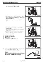
6.
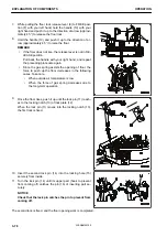
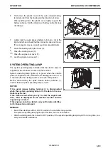
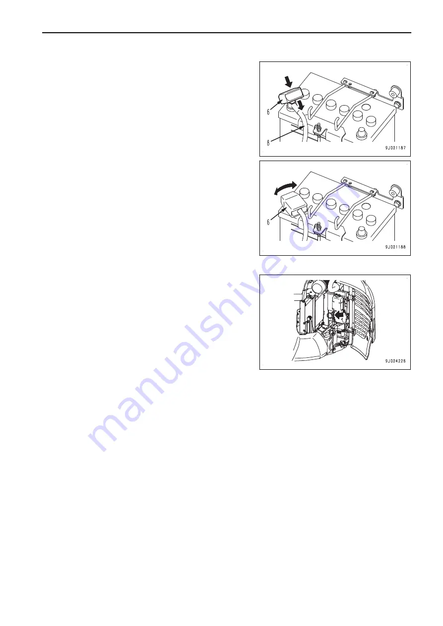
Push down the plastic cover of the quick release battery
terminal (-) (6) from the top toward the direction of arrow.
When pushing down the plastic cover, lightly support the
battery cable so that the direction of battery cable (8) does
not change.
7.
Lightly rock the quick release battery terminal (-) (6) to the
right and left, and check that the connector does not move.
If the connector moves, consult your Komatsu distributor.
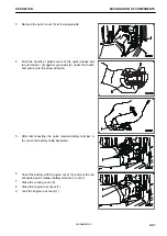
8.
Cover the battery with nylon cover (5).
9.
Close the cooling cover (3).
10. Close the engine rear cover (1).
11. Lock the engine rear cover (1).
SYSTEM OPERATING LAMP
The system operating lamp indicates that the electric power is
supplied to the controller mounted on the machine.
System operating lamp lights up in green when the electric
power is supplied to the controller, and usually goes out in 1 to
2 minutes after the starting switch is turned to OFF position.
Before disconnecting the quick release battery terminal (-),
confirm that the system operating lamp is not lit.
NOTICE
If the quick release battery terminal (-) is disconnected
while the system operating lamp is lit, the data in the con-
troller may be lost.
If the data are lost, when you try to start the engine next
time, “L04” is displayed on the machine monitor and the
engine may not start.
If the engine cannot be started, ask your Komatsu distribu-
tor for inspection and repair.
REMARK
• Even if the starting switch is in OFF position, the controller may operate.
The system operating lamp lights up at this time, but it is not a failure.
• After the starting switch is turned to OFF position, if the system operating lamp stays lit for a long time, con-
sult your Komatsu distributor.
OPERATION
EXPLANATION OF COMPONENTS
3-89
WENAM00150
Содержание PC30MR-5
Страница 2: ......
Страница 66: ...WENAM00150 ...
Страница 69: ... 14 Engine rear cover 15 Cooling cover 16 Battery OPERATION GENERAL VIEW 3 3 WENAM00150 ...
Страница 257: ...MAINTENANCE Please read and make sure that you understand the SAFETY section before reading this section 4 1 WENAM00150 ...
Страница 324: ...The accumulator is installed to the position shown in the figure MAINTENANCE PROCEDURE MAINTENANCE 4 68 WENAM00150 ...
Страница 325: ...SPECIFICATIONS 5 1 WENAM00150 ...
Страница 363: ...REPLACEMENT PARTS 7 1 WENAM00150 ...
Страница 370: ...WENAM00150 ...
Страница 379: ......
Страница 380: ......


