Chapter 5 Installation
MDC-2000 Series
5-10
0093120005-02
5.2
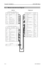
Mutual Connection Diagram
Antenna
Display unit
RB715A/RB716A:X11, RB717A/RB718A:J2
Remark
Color of lead wire
No.
No.
Color of lead wire
Remark
+250 V
VIOLET
1
1
VIOLET
+250 V
NC -
2
2
BLUE
+24V
GND
YELLOW
3
3
ORANGE (wide cable)
+12V
+40V
RED (wide cable)
4
4
YELLOW
GND
+40V YELLOW
(wide
cable) 5
5
Shied
DAT-R
+40V-R
GREEN (wide cable)
6
6
RED (coaxal cable)
DAT
+40V-R
BLUE (wide cable)
7
7
-
NC
8
BROWN (coaxal cable)
BP/SHF
RB715A/RB716A:X12, RB717A/RB718A:J1
9
Shied
BP/SHF-R
Remark
Color of lead wire
No.
10
GRAY (coaxal cable)
V/TRG
+24V BLUE
1
11
-
NC
NC -
2
12
RED(wide
cable) +40V
+12V
ORANGE (wide cable)
3
13
YELLOW (wide cable)
+40V
DAT-R Shied
4
14
Shied
V/TRG-R
DAT
RED (coaxal cable)
5
15
GREEN (wide cable)
+40V-R
BP/SHF-R
Shied
6
16
BLUE (wide cable)
+40V-R
BP/SHF
BROWN (coaxal cable)
7
V/TRG-R Shied
8
V/TRG
GRAY (coaxal cable)
9
GND
Terminal
GND Shied
1
Содержание MDC-2000 series
Страница 1: ......
Страница 2: ......
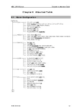
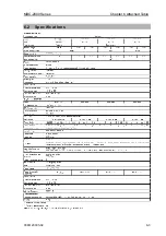
Страница 72: ...MDC 2000 Series Chapter 6 Attached Table 0093120005 02 6 1 Chapter 6 Attached Table 6 1 Menu Configuration ...
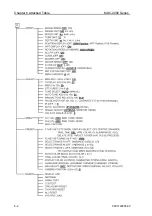
Страница 73: ...Chapter 6 Attached Table MDC 2000 Series 6 2 0093120005 02 ...
Страница 74: ...MDC 2000 Series Chapter 6 Attached Table 0093120005 02 6 3 6 2 Specifications ...
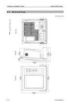
Страница 75: ...Chapter 6 Attached Table MDC 2000 Series 6 4 0093120005 02 6 3 External View Unit mm inch ...
Страница 82: ......

