background image

1 - 7

Chapter 1.   Getting Started

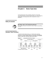
Setting Up the Printhead

Setting Up the Printhead

Proper printhead setup helps to ensure print quality. 

Determining Substrate Movement

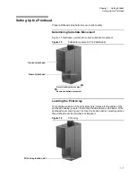
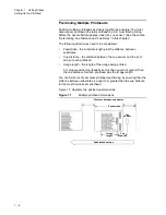
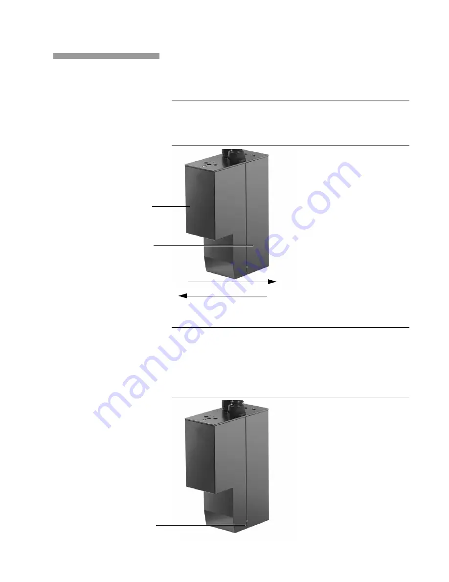
Figure 1.5 illustrates normal and reverse substrate movement.

Figure 1.5

Substrate movement (7122 printhead)

Locating the Print Array

To locate the position of the print array (jets) relative to the edges of the 
printhead housing (covers), locate the dot indentation on the seam of the 
printhead cover (see Figure 1.6). Use the location dot to correctly position 
the printhead over the mailbase or transport.

Figure 1.6

Print array

Normal substrate movement

Reverse substrate movement

Front of printhead

Rear of printhead

Print array location dot

Содержание VERSAMARK DP7122

Страница 1: ...Kodak Versamark Inc KODAK VERSAMARK DP7122Printer Operator s Guide ...

Страница 2: ......

Страница 3: ...KODAK VERSAMARK DP7122 Printer Operator s Guide Block 3 Mod 11 ...

Страница 4: ...e radio interference in which case the user may be required to take adequate measures KODAK VERSAMARK DP7122 Printer Operator s Guide Copyright 2004 Kodak Versamark Inc All rights reserved This document contains proprietary information of Kodak Versamark Inc or its licensors and is their exclusive property It may not be reproduced without a written agreement from Kodak Versamark Inc No patent or o...

Страница 5: ...inter that can operate with compatible KODAK VERSMARK controllers as well as with user designed or third party controllers This guide assumes that the reader is the operator who is responsible for printing jobs troubleshooting common printing problems and performing routine maintenance The reader should have a basic knowledge of computers and the printing environment in which the printer is being ...

Страница 6: ...ent hazard that will result in serious injury or death This style Refers to Ready Text displayed by the software go Anything you type exactly as it appears whether referenced in text or at a prompt ENTER Special keys on the keyboard such as enter alt and spacebar NEXT Buttons and lights on the printer operator panel Save Software command buttons and sections of dialog boxes such as group boxes tex...

Страница 7: ...for telephone or on site technical support to order parts or supplies to request documentation or product information Phone Fax U S A Canada and worldwide 1 800 472 4839 1 937 259 3739 1 937 259 3808 Europe 41 21 806 0404 41 21 806 1920 Asia Pacific Rim 65 6744 6400 65 6744 6700 Japan 81 3 3256 2613 81 3 3256 2616 Updated service information http www kodakversamark com Customer support customer ko...

Страница 8: ......

Страница 9: ...hapter 2 Basic Operation Safety Information 2 1 Operator Panel Functions 2 1 Panel Buttons 2 2 Panel Lights 2 3 Operating Procedures 2 3 Turning On the Printer 2 4 Bypassing the POC Test and Fluid System 2 4 Turning On the Fluid System When Idle 2 4 Turning On the Fluid System When Bypassed 2 5 Idle Time Guidelines 2 5 Turning Off the Fluid System 2 5 Turning Off the Printer and the Fluid System 2...

Страница 10: ...er Print Density 3 13 Chapter 4 Maintenance Safety Information 4 1 Required Tools and Supplies 4 2 Periodic Maintenance 4 2 Cleaning the Printhead 4 2 Cleaning the Air Filter 4 3 Replacing the Mist and Fluid Filters 4 3 Corrective Maintenance 4 4 Cleaning the Bottom Cover 4 5 Catch Pan Installation 4 6 Standby Pan Installation 4 7 Wiping and Swabbing 4 8 Routine Cleaning 4 8 Incident Recovery 4 10...

Страница 11: ...caused missing print sample test pattern 3 6 Figure 3 5 Crooked jets sample test image and test pattern 3 8 Figure 3 6 Slight streaker sample test pattern 3 9 Figure 3 7 Open sample test pattern 3 9 Figure 3 8 Slight dark defect sample test pattern 3 10 Figure 3 9 Slight pickout sample test pattern 3 10 Figure 3 10 Phase defect sample test patterns 3 11 Figure 3 11 Compressed test image 120 ppi 3 ...

Страница 12: ...Contents Tables xii Kodak Versamark DP7122 Printer Tables Table 1 1 Maximum distances 1 11 Table 2 1 Operator panel buttons 2 2 Table 2 2 Operator panel lights 2 3 Table 2 3 Idle time guidelines 2 5 ...

Страница 13: ...tion Introduction Printer Components Supporting the Printhead Setting Up the Printhead Determining Substrate Movement Locating the Print Array Positioning Multiple Printheads Determining Cue Distance and Cue Delay Document and Image Lengths Before starting any printer procedure read the safety information ...

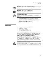
Страница 14: ...safety precautions see Figure 1 1 Take appropriate safety precautions at all times Note the safety label symbols listed below these warning symbols are used on the printer and printhead for general reference and in the text to identify hazards related to specific procedures or actions Figure 1 1 Safety label locations 7122 printer and printhead Warning Electrostatic Sensitive Devices Avoid generat...

Страница 15: ...g 100 percent variable data at a print speed of up to 1000 fpm depending on the application After installation basic setup procedures must be performed before printing can begin Along with a brief overview of the printer components this chapter describes the required setup procedures which include supporting the printhead setting up the printhead positioning multiple printheads and determining cue...

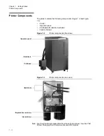
Страница 16: ...tor panel Printhead with attached umbilical Fluid containers Figure 1 2 Printer components front view Figure 1 3 Printer components rear view Note Your fluid containers make differ from those shown above See the 7122 Printer Changing Fluid Containers document for details Umbilicals Printhead Operator panel Umbilicals Replenisher container Ink container ...

Страница 17: ... eyelid protects the print array from damage and dust and keeps fluids from leaking during printer startup and shutdown The printhead contains an eyelid heater which maintains the proper eyelid temperature Note Once it opens the eyelid remains open at all times including during Standby The eyelid closes only during startup and shutdown Because the eyelid remains open the Standby pan should be plac...

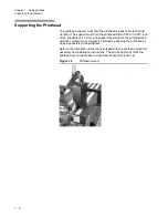
Страница 18: ...375 inch of the substrate 6 10 mm and support the weight of the printhead and umbilical Optimum print quality is obtained by keeping the printhead as close as possible to the substrate Refer to the installation instructions shipped with the printhead mount for assembly and installation instructions The printhead mount holds the printhead over a label base or document transport Figure 1 4 Figure 1 ...

Страница 19: ...vement 7122 printhead Locating the Print Array To locate the position of the print array jets relative to the edges of the printhead housing covers locate the dot indentation on the seam of the printhead cover see Figure 1 6 Use the location dot to correctly position the printhead over the mailbase or transport Figure 1 6 Print array Normal substrate movement Reverse substrate movement Front of pr...

Страница 20: ...e between substrates Cue distance the distance between the cue sensor and the print array of each printhead Image length the length of the image being printed For proper positioning feedstroke must be equal to or greater than the cue distance for each printhead plus the image length You can further verify accurate printhead positioning by ensuring that the distance between substrates is equal to o...

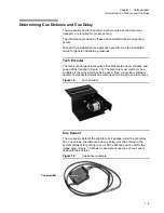
Страница 21: ...ates pulses that indicate the travel distance and speed of the transport Figure 1 8 The tach rate must match or be a multiple of the print resolution being used See your system software operator s manual for details on selecting print resolution and tach rate Figure 1 8 Tach encoder Cue Sensor The cue sensor detects the substrate as it passes under the print array Two cue values cue distance and c...

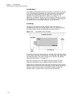
Страница 22: ...ure 1 10 The value entered for cue delay is based on the image position required for the job Figure 1 10 Cue distance and cue delay The minimum value for cue delay is zero A value of zero causes printing to start right at the edge of the substrate The maximum value allowed for cue delay depends on the print resolution in the direction of substrate movement See Table 1 1 on page 1 11 Enter the cue ...

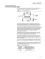
Страница 23: ...ive area such as a preprinted area is reached If printing on a web the start of document signal may come from a cue mark on the web or from a mechanical cue generator In this case the document length is used as an end of document indicator The maximum image length is fixed by the physical size of the printer page buffer and is dependent on the horizontal resolution being used Maximum image length ...

Страница 24: ......

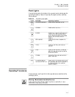
Страница 25: ...perform basic operating procedures such as turning the printer on and cleaning the printhead Figure 2 1 Using the buttons and lights on the panel you can perform specific functions and monitor the printer s performance Figure 2 1 Operator panel buttons and lights Mandatory Action Consult Operator s Manual Read all safety information and operator procedures through before performing any action Stan...

Страница 26: ...ormed Table 2 1 describes the functions associated with each button and identifies the On and Off positions for each button Table 2 1 Operator panel buttons Button Name On Position Off Position STANDBY If the fluid system is off turns on the fluid system eyelid open Light is on If the fluid system is on turns off the fluid system eyelid remains open Light is off TEST PRINT Starts printing test pat...

Страница 27: ...error remains lit for other standard printer errors Errors are listed in the Service Guide or the controller software manual DATA READY Lights up when data is available for printing TACH Lights up each time a tach pulse is received CUE Lights up each time the cue changes state Cue signals cannot be received without tach pulses POWER Lights when the printer has electrical power connected SOLVENT ER...

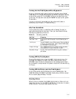
Страница 28: ... successful repeat the power on procedure a minimum of three times before requesting assistance from service personnel Bypassing the POC Test and Fluid System The printer can be turned on with the fluid system bypassed Use this method when the printer is to remain idle for more than 1 hour or during troubleshooting To turn the printer on with the fluid system and POC test bypassed press and hold O...

Страница 29: ...he STANDBY goes off when the fluid system is completely powered down No ink remains in the printhead The printer can be left in this state for up to 3 hours Turning Off the Printer and the Fluid System To turn off the printer and the fluid system press PRINTER ON The PRINTER ON and STANDBY lights flash rapidly and go off when power off is complete approximately 1 minute Clearing Errors When an err...

Страница 30: ...ally power back on To turn on the printer and the fluid system press PRINTER ON The power on cycle is performed See your system software operator s manual for information on restarting a job Figure 2 2 Printer rear view Note Your fluid containers make differ from those shown above See the 7122 Printer Changing Fluid Containers document for details Warning Flammable Material Never expose the printe...

Страница 31: ... the following troubleshooting procedures Printing test patterns Identifying print defects These procedures apply to the production 7122 printhead with the PAWS line for additional vacuum on the catcher face and anti wicking channels in the catcher body ...

Страница 32: ...procedures used to correct the printing problems are described in Chapter 4 Other corrective actions are referenced as required Use the following procedure to print test patterns or test image from the printer operator panel 1 Turn on the printer and the fluid system by pressing PRINTER ON 2 Press OPEN EYELID Ready to bring the fluid system to Ready 3 Press TEST PRINT The TEST PRINT light comes on...

Страница 33: ...s are not absolute Different problems can produce similar defects and more than one print defect can be present at the same time The groups are intended to provide general guidelines for identifying the cause of a given defect All print defects are shown using the standard test pattern and test image printed by the 7122 as described in Printing Test Patterns Run test patterns and compare them to t...

Страница 34: ...the following locations is a primary cause of poor print quality Eyelid seal Orifice plate Printhead bottom cover Figure 3 2 shows the eyelid seal The knife edge seal makes contact with the chamfer on the pan below the catcher Figure 3 2 Seal removed 7122 printhead eyelid Knife edge seal Front edge seal ...

Страница 35: ...ning Startup caused by dried ink buildup on a shut down system Slight Raggedness Dried ink buildup on eyelid seal or catcher edge will cause slightly ragged print The normal clean cycle should prevent it see Standby Pan Installation in Chapter 4 Maintenance Persistent raggedness may require swabbing Figure 3 3 shows mild raggedness on the upper portion of a test pattern run at 130 volts and 41 pha...

Страница 36: ...nthead Buildup Missing Print After a shut down or during intermittent operation dried ink residue builds up and causes a defect that resembles phase defect Figure 3 4 shows this defect on a series of four pieces printed at 130 volts and 41 phase counts The defect may diminish during operation as the dried ink dissolves A milder form of buildup causes startup raggedness or generally poor print qual...

Страница 37: ...3 7 Chapter 3 Troubleshooting Identifying Print Defects Figure 3 4 continued ...

Страница 38: ...rint Defects Crooked Jets Misaligned jets can be caused by contamination Figure 3 5 shows a slightly crooked jet also called a high jet Cleaning should correct a crooked jet Figure 3 5 Crooked jets sample test image and test pattern Crooked jets ...

Страница 39: ...nted at 155 volts and 37 phase counts Figure 3 6 Slight streaker sample test pattern Open Jets A clogged jet does not print producing an open spot in the test pattern Open jets are typically caused by contamination on the orifice plate Cleaning should correct an open jet Figure 3 7 shows an open jet Note An open jet should not be confused with an open charge lead An open charge lead one that never...

Страница 40: ...or extra drops both called dark defect Figure 3 8 shows dark defect on a test pattern run at voltage 115 and phase 41 Increase the voltage to eliminate dark defect Figure 3 8 Slight dark defect sample test pattern Pickout Charge voltage that is too high typically causes missing or misdirected drops called pickout or light defect Figure 3 9 shows pickout on a test pattern run at voltage 135 and pha...

Страница 41: ...at 160 volts and 25 phase counts changing as phase is increased to 35 The very slight remaining phase defect disappeared at 40 phase counts Figure 3 10 Phase defect sample test patterns Setup Errors The following common system setup errors produce print defects Narrow print Elongation Truncation Narrow Print An input tach rate that is too fast for the set resolution produces compressed characters ...

Страница 42: ...inch If the test images print correctly change the job setup to orient the image properly on the substrate Miscellaneous Problems The following problems can be produced by various causes Interference Irregular gaps Single line of dots Smears Distortion Improper print density The following sections describe the typical cause of each problem and normal corrective action Interference Interference app...

Страница 43: ...e has passed under the printhead Smears can also be caused by improper printhead height See Chapter 1 If the printhead is too low it can pick up ink from the printed pieces Verify that the software parameter for printhead height matches the actual physical printhead height adjust the printhead height parameter to match the printhead s position as required Distortion Distortion appears on test prin...

Страница 44: ......

Страница 45: ...ure the printer continues to operate properly As operator you perform two types of routine maintenance on the printer daily and periodic Corrective maintenance procedures are performed to correct printing problems as directed by the troubleshooting procedures described in Chapter 3 Safety Information Mandatory Action Consult Operator s Manual Read all safety information and operator procedures thr...

Страница 46: ...s of deteriorating quality after a printhead clean To correct a problem that does not respond to normal cleaning apply the following guidelines With the printer in ready clean the eyelid seal If the problem persists swab the printhead after doing a shutdown see Identifying Print Defects in Chapter 3 Caution The only time the printhead should be swabbed is when it exhibits severe raggedness or croo...

Страница 47: ...gure 4 1 Removing the air filter 2 Rinse the air filter in tap water shaking out the excess water 3 Air dry or use compressed air to dry the air filter 4 When the air filter is completely dry seat the bottom edge of the filter in the lower bracket and press down on the upper edge of the air filter until it slips under the upper bracket Replacing the Mist and Fluid Filters The mist filter and the i...

Страница 48: ...g and swabbing Before starting to clean the printhead read all the safety information Warning Electrostatic Sensitive Devices Avoid generating static electricity Static can ignite ink replenisher or vapor Strictly follow all grounding instructions Warning General Danger Read all safety information and operator procedures through before performing any action Warning Irritant Avoid contact with all ...

Страница 49: ...ress STANDBY 2 Press OPEN EYELID Ready 3 Put the printhead in its service position to access the bottom cover see Figure 4 2 4 Remove the printhead bottom cover by inserting an index finger into the slot on the bottom cover and carefully pulling the cover off 5 Use foam swab and replenisher to clean the bottom cover the catcher bottom plate and the eyelid especially its seal 6 Press CLEAN PRINTHEA...

Страница 50: ... be used but it will not stick on a housing that is coated with ink Early printheads also required the SERVICE CATCH PAN ADAPTER 0190763 to attach the pan The pan cannot be installed with the rear cover removed 4 Connect the catcher line to the catch pan fitting see Figure 4 4 5 Connect the wrist strap ground line to a port on the printhead manifold 6 Plug the ground cable 0190803 into the port on...

Страница 51: ...e standby pan see Figure 4 5 Figure 4 5 Standby pan 0194687 with grounding wire Use the following procedure to install the standby pan 1 Bring the system to ready then go to standby 2 Connect the ground wire 0195253 to a stud on the printer back panel 3 Lift the printhead enough the clear the drip pan Wrist strap ground Catch pan ground Catcher line connection Standby pan Warning Flammable Materia...

Страница 52: ...ried ink should always be the first step in any effort to correct a print quality problem Routine Cleaning During normal operation ink will collect on the lower surfaces of the printhead from mist or spray produced by the curtain of drops falling to the substrate The clean cycles run during shutdown should remove this ink before it becomes a problem Inspect the printhead periodically to see if the...

Страница 53: ... printhead running replenisher Swabbing 7 If the jet curtain shows any print irregularities clean it with a foam swab Start in the middle of the array holding the swab at a 45 angle to the array and draw it along the printhead to remove buildup from the eyelid seal orifice plate see Figure 4 8 and catcher lip see Figure 4 7 Caution Use each swab only once the foam disintegrates after prolonged exp...

Страница 54: ...llect more ink usually at the start of a job Strands or strings between the catcher and eyelid Eventually ink buildup will cause the entire print array to become ragged Shorting on Startup 3 If the printhead is repeatedly shorting during a startup do a printhead clean then a startup The printhead clean is a shorter version of the cleaning down during a shutdown that uses less replenisher 4 Repeat ...

Страница 55: ...eyelid bring the system up and run more test patterns to check that cleaning eliminated the problem 15 If the problem has been reduced but not eliminated adjust the charge voltage to minimize the defect If that does not eliminate the defect repeat the cleaning procedure 16 If cleaning and running a printhead clean do not prevent shorting do another shutdown and startup 17 If the printhead still di...

Страница 56: ......

Страница 57: ...lay The distance from the leading edge of a piece to the start of the image cue distance The distance from the cue sensor to the print array cue error A parameter in the system software that allows the operator to determine how a cue or piece overrun error is handled cue mark A pre printed mark on a web that in most cases indicates the start of a new document cue sensor A device mounted on the doc...

Страница 58: ...o determine where an image is printed on the substrate Feedstroke equals the piece length plus the distance between pieces filament A short continuous stream of ink extending from the orifice which is broken into drops by the measured application of a physical vibration fluid compartment The area inside the printer cabinet that contains the ink and replenisher containers fluid supply The ink and r...

Страница 59: ...ps for return to the fluid cabinet The printhead receives data in bitmap format and using ink and charge voltages creates inkjet images print width The maximum width of the area that can be printed by the printhead usually provided in inches or dots printhead height The distance between the bottom of the printhead and the substrate replenisher A fluid used to maintain the proper concentration of i...

Страница 60: ...int A series of printed characters that the printer operator compares against the text produced by the printer to troubleshoot printing problems umbilical The part of the printer that transfers the fluids and signals between the fluid system and the printhead through an assembly of hoses and wiring encased within a flexible protective shield voltage defect A printing problem that is caused by an i...

Страница 61: ......

Страница 62: ...0114130 602 0114130 603 Kodak Versamark Inc ...

Отзывы: